Transmission for a car

A technology for transmission and vehicle, applied in the direction of vehicle transmission, vehicle components, components with teeth, etc., can solve problems such as complex structure, and achieve the effects of reducing pollution, reducing vibration sensitivity, and being easy to manufacture.

Inactive Publication Date: 2011-09-21
GM GLOBAL TECH OPERATIONS LLC
View PDF11 Cites 2 Cited by
  • Summary
  • Abstract
  • Description
  • Claims
  • Application Information

AI Technical Summary

Problems solved by technology

The structure

Method used


Image

  • Transmission for a car
  • Transmission for a car
  • Transmission for a car

Examples


Embodiment Construction

[0091] In the following description, embodiments of the present application will be described in detail. It will be apparent, however, to one skilled in the art that the embodiment may be practiced without these details.

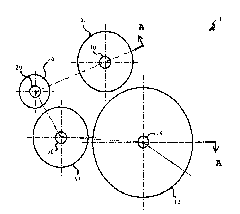
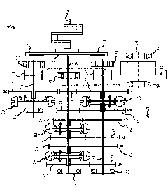
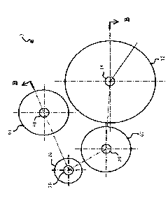
[0092] Figure 1-2 A detailed description of a first embodiment of the transmission 1 of the present application is provided.

[0093] The transmission 1 comprises a larger output gear 12 on an output shaft 14 , an input shaft 20 and two pinions 41 , 51 on two layshafts 40 , 50 . The input shaft 20 is non-rotatably connected to the clutch disc 8 of the clutch 6 . The two pinions 41 , 51 are the upper pinion 41 or reverse pinion 41 , and the lower pinion 51 or layshaft pinion 51 . On their axes of rotation, the upper pinion 41 is fixed to the upper layshaft 40 or reverse layshaft 40 and the lower pinion is fixed to the lower layshaft 50 or layshaft 50 , respectively. The two pinions 41 , 51 mesh with the output gear 12 at different positions of the output...


PUM


Abstract

A transmission, for a car, has a first gearwheel group that comprises a fixed gearwheel first gear 2 on an input shaft 20 and that is meshing with an idler first gear 36 on a first layshaft 50. The transmission further comprises a reverse gearwheel group having an idler reverse gear 61 on a second layshaft 40, the idler reverse gear 61 meshing with the idler first gear 36 on the first layshaft 50, wherein gearwheels of a second gearwheel group, of a third gearwheel group, and of a fourth gearwheel group are arranged on the input shaft 20 and on the first layshaft 50.

Description

technical field [0001] The invention relates to a transmission for a vehicle. Background technique [0002] A transmission typically includes an input shaft connected to and actuated by a clutch pack driven by an electric or combustion engine. [0003] FR 2,770,599 and EP 1,270,996 show gearboxes with two layshafts, only one of which carries the pinion for the output gear. The gearbox of FR 2,770,599 is complex because separate fixed wheels on the input and output shafts are provided for torque transmission in reverse mode. The gearbox of EP 1,270,996 provides a first fixed reverse gear, which meshes with a second idler reverse gear, which in turn is connected with the first idler reverse gear, and the first and second idler reverse gears are connected with The second reverse gear fixed wheel is arranged on the same axis, and the second reverse gear fixed wheel meshes with the first gear fixed wheel on the input shaft. For reverse mode, it is necessary to actuate a coupli...

Claims


Application Information

Patent Timeline
IPC IPC(8): F16H3/093F16H3/12B60K17/06
CPCF16H3/093F16H2003/0931F16H2200/0047F16H2200/0052F16H3/089Y10T74/19233
Inventor 马库斯·罗肯贝克约瑟夫·豪
Owner GM GLOBAL TECH OPERATIONS LLC
Why Eureka
Try Eureka