Flat pipe heat exchanger and assembly method thereof

An assembly method and heat exchanger technology, applied in the direction of assembly machines, tubular elements, heat exchange equipment, etc., can solve the adverse effects of fin and flat tube bonding, reduce the heat dissipation efficiency of heat exchanger, and the influence of fin flanging is relatively large Large and other problems, to achieve the effect of easy processing, simple structure and easy assembly

Inactive Publication Date: 2011-09-21
LG ELECTRONICS (TIANJIN) APPLIANCES CO LTD
View PDF4 Cites 17 Cited by
  • Summary
  • Abstract
  • Description
  • Claims
  • Application Information

AI Technical Summary

Problems solved by technology

[0005] In the prior art, when assembling, the fins are stacked first, and then the flat tubes are inserted vertically for assembly; the insertion stroke of the flat tubes from the lower end to the top of the fins is relatively large, which has a great influence on the flanging of the fins, resulting in It is difficult to determine the spacing of the fins, which will adversely affect the fit between the fins and the flat tubes and reduce the heat dissipation efficiency of the heat exchanger

Method used


Image

  • Flat pipe heat exchanger and assembly method thereof
  • Flat pipe heat exchanger and assembly method thereof
  • Flat pipe heat exchanger and assembly method thereof

Examples


Embodiment Construction

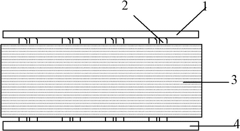
[0032] The structure of the heat exchanger of the present invention will be further described below with reference to the accompanying drawings.

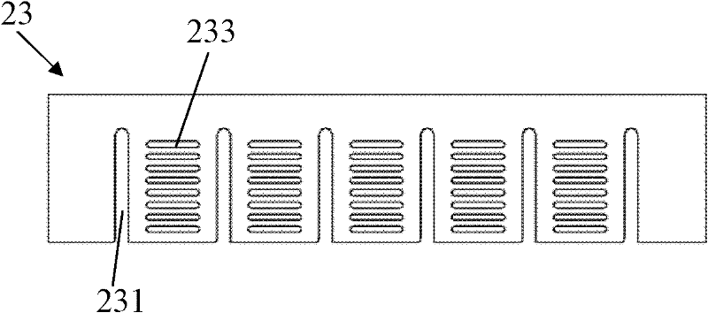
[0033] Such as image 3 As shown, the fin 23 is a rectangular aluminum sheet, on which a plurality of groups of punching holes 233 are evenly spaced, and the punching holes 233 are set along the length direction of the rectangular fin, and the punching holes 233 are conducive to the air flow inside. Through to enhance the cooling effect of the radiator. Between the two groups of punching holes 233, there is a "U"-shaped pipe groove 231, the openings of the pipe groove 231 are all set on the same side of the fin 23, and a flange 232 is arranged around the pipe groove 231, wherein , the width of the duct groove 231 is slightly greater than the thickness of the flat tube 22 described below, generally 0.5-1mm larger than the thickness of the flat tube 22, that is, the flat tube 22 can smoothly enter the duct groove 231; the width of th...


PUM


Abstract

The invention discloses a flat pipe heat exchanger. The flat pipe heat exchanger comprises fins provided with pipe channel slots, and flat pipes which are fixedly connected with the fins; each pipe channel slot is U-shaped; the pipe channel slots are provided with flangings; and the side wall of the flat pipe is provided with fixed inclined sides corresponding to the flangings. The invention also discloses an assembly method of the flat pipe heat exchanger. The method comprises the following steps of: 1) fixing the flat pipes at intervals corresponding to the pipe channel slots; 2) horizontally pushing the fins into the flat pipes; 3) clamping the fixed inclined sides by using a clamping device to ensure that the fixed inclined sides are tightly connected with the flangings; 4) continuously inserting the next fin; and 5) connecting two ends of the flat pipes and an inlet collecting pipe and an outlet collecting pipe respectively to finish assembly. The flat pipes are inserted in the horizontal direction, the travel of the flat pipes are shortened, one fixed inclined side is formed on the surface of each flat pipe aiming at each fin, the fixed inclined sides can clamp the flangings of the fins by using the clamp device to ensure the contact areas between the fixed inclined sides and the flangings, high and uniform heat radiation effect is achieved, and product performance is improved.

Description

technical field [0001] The invention relates to a heat exchanger, in particular to an aluminum flat tube heat exchanger and an assembly method thereof. Background technique [0002] When the room air conditioner is running in cooling mode, the indoor air flows through the evaporator to reduce the temperature. At the same time, because the temperature of the surface of the evaporator is generally significantly lower than the dew point temperature of the air, when the air flows through the surface of the evaporator, part of the moisture in the air will be precipitated, thereby forming condensed water on the surface of the evaporator. The condensed water on the surface of the evaporator should be drained in time. If the condensed water accumulates on the surface of the evaporator, it will block the air flow channel, increase the flow resistance of the air, and reduce the efficiency of the evaporator: water droplets may also blow into Indoor conditions lead to substandard quali...

Claims


Application Information

Patent Timeline
Patent Type & Authority Applications(China)
IPC IPC(8): F28F1/30B23P21/00
Inventor 崔静车金峰
Owner LG ELECTRONICS (TIANJIN) APPLIANCES CO LTD
Why Eureka
Try Eureka