Device and method for judging near field distance
A near-field distance and judging device technology, which is applied in the direction of measuring devices, instruments, and re-radiation, can solve the problems of high system requirements, large amount of mathematical calculation, weak anti-interference ability, etc., and achieve simple device setting and simple calculation process , the effect of small amount of calculation
- Summary
- Abstract
- Description
- Claims
- Application Information
AI Technical Summary
Problems solved by technology
Method used
Image
Examples
Embodiment 1
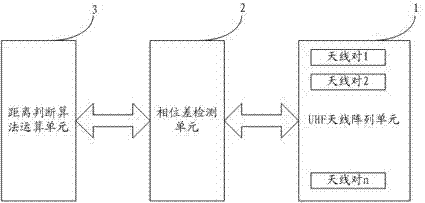
[0079] Figure 4 It is a schematic diagram of the antenna distribution of the UHF antenna array unit 1 in Embodiment 1 of the near-field distance judging device of the present invention. like Figure 4 As shown, UHF antenna array unit 1 includes 4 sets of positioning antenna pairs (ANT1, ANT3), (ANT3, ANT7), (ANT7, ANT5), (ANT5, ANT1) and 4 sets of height-fixed antenna pairs in the same plane (ANT1, ANT2), (ANT3, ANT4), (ANT5, ANT6), (ANT7, ANT8); Antennas ANT1, ANT3, ANT5, and ANT7 are respectively used for 2 sets of positioning antenna pairs and 1 set of height-fixing antenna pairs. ANT2, ANT4, ANT6, and ANT8 are only used for one set of height-fixed antenna pairs; positioning antenna pairs (ANT1, ANT3), (ANT3, ANT7), (ANT7, ANT5), (ANT5, ANT1) between the two antennas The center line of the connection intersects at one point the extension line of the connection between the two antennas of the fixed-height antenna pair (ANT1, ANT2), (ANT3, ANT4), (ANT5, ANT6), (ANT7, ANT8)...
Embodiment 2
[0086] Figure 10 It is a schematic diagram of the antenna distribution of the UHF antenna array unit 1 in the second embodiment of the near-field distance judging device of the present invention. like Figure 10 As shown, the UHF antenna array unit 1 includes 3 sets of positioning antenna pairs (ANT3, ANT4), (ANT7, ANT8), (ANT9, ANT10) and 3 sets of height-fixed antenna pairs (ANT1, ANT2) in the same plane, (ANT5, ANT6), (ANT11, ANT12); Antennas ANT3, ANT4, ANT7, ANT8, ANT9, ANT10 are only used for 1 pair of positioning antennas, and antennas ANT1, ANT2, ANT5, ANT6, ANT11, ANT12 are used for 1 pair respectively. The use of fixed-height antenna pairs; positioning antenna pairs (ANT3, ANT4), (ANT7, ANT8), (ANT9, ANT10) The midline of the connection between the two antennas, and the fixed-height antenna pair (ANT1, ANT2), ( The extension line between the two antennas of ANT5, ANT6), (ANT11, ANT12) intersects at one point; locate the line connecting the midpoint of the antenna ...
Embodiment 3
[0090] Figure 11 It is a schematic diagram of the antenna distribution of the UHF antenna array unit 1 in Embodiment 3 of the near-field distance judging device of the present invention. like Figure 11As shown, UHF antenna array unit 1 includes 4 sets of positioning antenna pairs (ANT3, ANT4), (ANT7, ANT8), (ANT9, ANT10), (ANT13, ANT14) and 4 sets of height-fixed antenna pairs (ANT1, ANT2) , (ANT5, ANT6), (ANT11, ANT12), (ANT15, ANT16); Antennas ANT3, ANT4, ANT7, ANT8, ANT9, ANT10, ANT13, ANT14 are only used for one pair of positioning antennas, and antennas ANT1, ANT2, ANT5, ANT6, ANT11, ANT12, ANT15, and ANT16 are only used for one set of fixed-height antenna pairs; The midline of the connection line between the two antennas intersects the extension line of the connection line between the two antennas of the height-fixed antenna pairs (ANT1, ANT2), (ANT5, ANT6), (ANT11, ANT12), (ANT15, ANT16) at One point; the line connecting the middle points of positioning antenna pai...
PUM
 Abstract
Description
Claims
Application Information
 - R&D
- Intellectual Property
- Life Sciences
- Materials
- Tech Scout
- Unparalleled Data Quality
- Higher Quality Content
- 60% Fewer Hallucinations
Browse by: Latest US Patents, China's latest patents, Technical Efficacy Thesaurus, Application Domain, Technology Topic, Popular Technical Reports.
© 2025 PatSnap. All rights reserved.Legal|Privacy policy|Modern Slavery Act Transparency Statement|Sitemap|About US| Contact US: help@patsnap.com


