Ion implanting system and method

An ion implantation system and ion implantation technology, applied in the field of ion implantation systems, can solve the problems of low transmission efficiency of high-energy ions, and the same system cannot be used for ion implantation applications, so as to improve transmission efficiency, save equipment costs, and save space. Effect

Inactive Publication Date: 2011-09-21
KINGSTONE SEMICONDUCTOR LIMITED COMPANY
View PDF8 Cites 11 Cited by
  • Summary
  • Abstract
  • Description
  • Claims
  • Application Information

AI Technical Summary

Problems solved by technology

[0011] The technical problem to be solved by the present invention is to overcome the defects that the transmission efficiency of the existing system for high-energy ions is too low and various ion implantation applications in the prior art cannot be performed by the same system, and provide

Method used


Image

  • Ion implanting system and method
  • Ion implanting system and method
  • Ion implanting system and method

Examples


Embodiment Construction

[0033] The preferred embodiments of the present invention are given below in conjunction with the accompanying drawings to describe the technical solution of the present invention in detail.

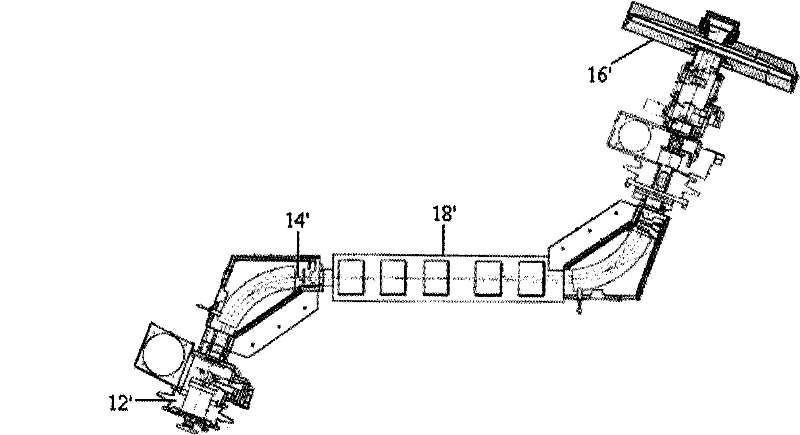
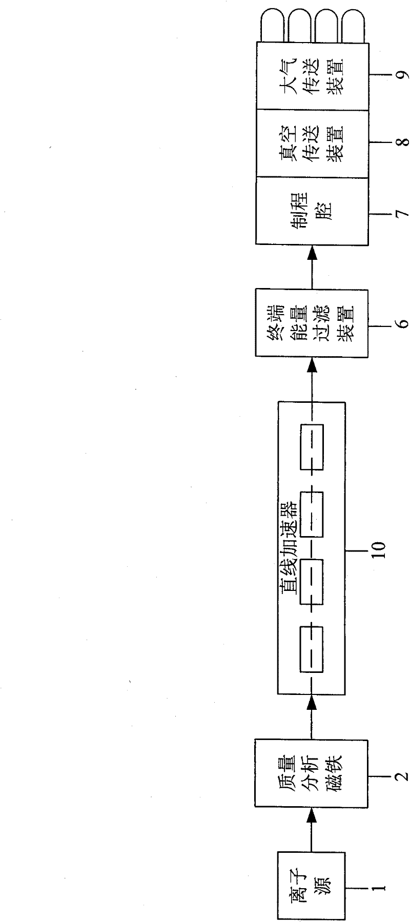
[0034] like Figure 5 As shown, the ion implantation system of the present invention is essentially a medium-dose ion implantation system formed by combining the existing high-energy ion implanter and medium-beam ion implanter. Refer to figure 2 and Figure 4 , the ion implantation system of the present invention includes the following devices identical to the existing medium-beam ion implanter:

[0035] An ion source 1, the ion source 1 is used to generate an ion beam; then on the transmission path of the ion beam, there are also:

[0036] A mass analysis magnet 2, which is used to select an ion beam within a preset energy range from the ion beam; a beam scanning device 3, which is used to scan the ion beam within the preset energy range in a certain dimension, It can adopt electric...


PUM


Abstract

The invention discloses an ion implanting system. The system comprises an ion source, a quality-analyzing magnet, a beam scanning device, a collimating device, a speed changing device and a manufacturing process cavity; and the system also comprises a rectilinear accelerator which is arranged between the quality-analyzing magnet and the beam scanning device and is used for accelerating an ion beam within a preset energy range by using a radio-frequency electric field and an energy filtering device which is arranged between the rectilinear accelerator and the beam scanning device and is used for improving the energy monochromaticity of the ion beam within the preset energy range. The invention also discloses an ion implanting method implemented by the ion implanting system. In the high-energy-ion implanting application, the transmission efficiency of the high-energy ion can be improved; and the system can be conveniently modified to be applicable for the implantation of a medium-energy ion beam.

Description

technical field [0001] The invention relates to an ion implantation system, in particular to an ion implantation system and method. Background technique [0002] Ion beam implanters are widely used in the ion doping process of semiconductor wafers. Ion beam implanters generate an ion beam consisting of ions of a desired type and impinge the beam on the surface of a semiconductor wafer workpiece, thereby "doping" or implanting the desired ions into the workpiece surface. [0003] The structure of an ion implanter for performing high-energy ion implantation is as follows figure 1 As shown, referring to the description of US Pat. No. 6,137,112, the high-energy ion implanter can generate an ion beam 14' with a beam energy of 10-5000 keV. Wherein, the implanter includes an ion source 12' for providing ions constituting an ion beam 14', and the ion beam is implanted into a workpiece or transported to a wafer processing chamber 16' through an ion beam transmission path. The impl...

Claims


Application Information

Patent Timeline
IPC IPC(8): H01J37/317
Inventor 陈炯
Owner KINGSTONE SEMICONDUCTOR LIMITED COMPANY
Why Eureka
Try Eureka