Rotary die bonding apparatus and methodology thereof

A chip combination and rotary technology, which is applied in the manufacture of electrical components, electrical solid devices, semiconductor/solid devices, etc., can solve problems such as low production volume and the influence of production capacity characteristics

Inactive Publication Date: 2011-09-21
沈亚容
View PDF4 Cites 19 Cited by
  • Summary
  • Abstract
  • Description
  • Claims
  • Application Information

AI Technical Summary

Problems solved by technology

Therefore, the throughput characteristics will be affected, and this will lead to low throughput

Method used


Image

  • Rotary die bonding apparatus and methodology thereof
  • Rotary die bonding apparatus and methodology thereof
  • Rotary die bonding apparatus and methodology thereof

Examples


Embodiment Construction

[0028] In the following detailed description, numerous specific details are set forth in order to provide a thorough understanding of the present invention. However, it will be understood by one skilled in the art or by one of ordinary skill in the art that the invention may be practiced without these details. In other instances, well-known methods, procedures and / or elements have not been described in detail so as not to obscure the present invention.

[0029] The invention will be understood more clearly from the following description of embodiments thereof, which are given by way of example only with reference to the accompanying drawings, which are not drawn to scale.

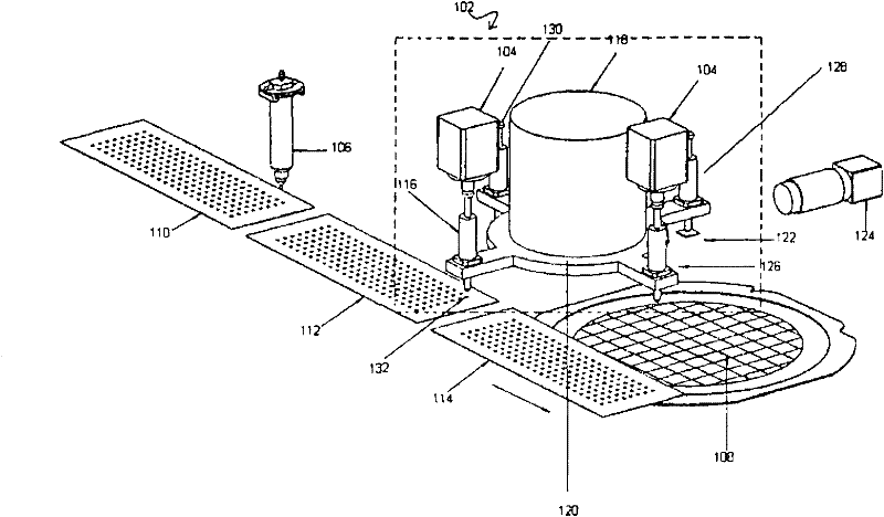
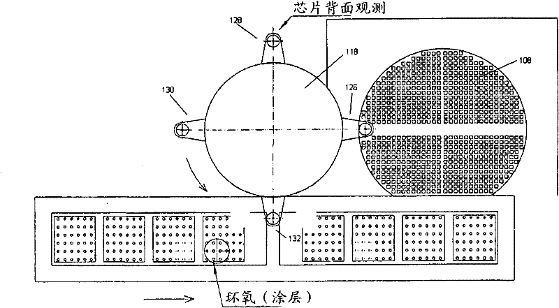
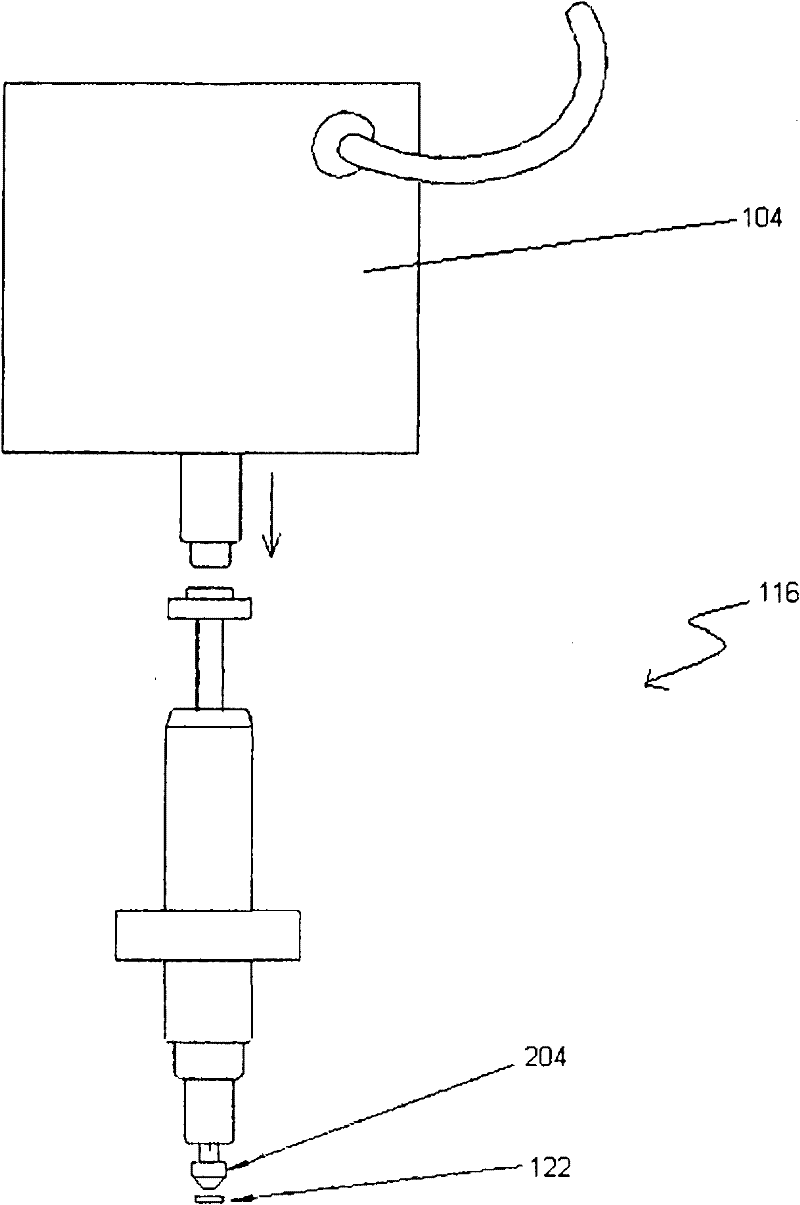
[0030] refer to figure 1 , showing a perspective view of the rotary die bonding apparatus 102 together with the image capture apparatus 124, the epoxy syringe 106, the die wafer ring 108, and the lead frames 112, 114; further illustrated by figure 2 Concrete, the figure 2 A top view of the rotary die b...


PUM


Abstract

The present invention relates generally to a rotary die bonding apparatus (102) comprising a vertical motion linear actuator and a rotary motion actuator with a plurality of pick up heads (116) for transferring semiconductor die (122) from diced wafer to the lead frame for die bonding process, wherein said plurality of pick up heads (116) performs its assigned task such as pick (126), die bonding (132), inspection (128) and others simultaneously upon reaching its specific location and rotates to another location upon completion of each task to perform the next assigned task.

Description

technical field [0001] The present invention generally relates to a rotary die bonding apparatus comprising a vertical motion linear actuator and a rotary motion actuator system, the rotary die bonding apparatus having a plurality of pick-up Picking heads, these pick-up heads are used to transfer semiconductor chips from diced wafers to lead frames for die bonding process, wherein the plurality of pick-up heads perform their prescribed tasks while reaching their specific positions, such as picking, die bonding, Check, etc., and turn to another position at the completion of each task to perform the next prescribed task. Background technique [0002] Typically, after a semiconductor chip is separated from a semiconductor wafer, or in other words, after wafer dicing, the chip will remain at the dicing tape until it is processed or extracted by chip handling equipment such as a die bonder or die sorter . The chip handling equipment performs tasks such as die attach whereby the...

Claims


Application Information

Patent Timeline
Patent Type & Authority Applications(China)
IPC IPC(8): H01L21/50H01L21/67
CPCH01L24/83H01L21/67144H01L2224/83H01L2224/838H01L2924/01082H01L2924/01006H01L2224/2919H01L2924/01033H01L2924/0665H01L24/75H01L2924/00
Inventor 沈亚容
Owner 沈亚容
Why Eureka
Try Eureka