Intracranial lesion computerized tomography (CT) body surface simple positioning method

A positioning method and body surface technology, applied in patient positioning for diagnosis, computerized tomography scanner, echo tomography, etc., can solve the problems of delaying rescue time, increasing treatment costs, expensive equipment, etc., and achieve good prognosis and recovery , shorten the positioning time, reduce the effect of tissue damage

Inactive Publication Date: 2011-09-28
姬西团 +1
View PDF0 Cites 4 Cited by
  • Summary
  • Abstract
  • Description
  • Claims
  • Application Information

AI Technical Summary

Problems solved by technology

Since most of the brain lesions are located in the deep part of the brain, even small lesions located in superficial parts, it is difficult to accurately locate them with traditional surgical methods, which makes accurate resection of intracranial lesions difficult.
Some intracranial lesions have unclear boundaries with the surrounding brain tissue and are difficult to identify even under a microscope. If the preoperative positioning is not accurate, it may be difficult to find during the operation
There have been many reports on intracranial lesion localization methods, such as scalp marking after CT and MRI scans, and then CT or MRI re-examination, using geometric principles for localization, but this method will delay rescue time, increase treatment costs, and sometimes suffers from Skull irregularities have a greater impact
In recent years, although neuronavigation technology and stereotaxic technology developed in the field of neuroscience can accurately locate intracranial lesions, the equipment of both is expensive and the operation is cumbersome, so it is not suitable for popularization in primary hospitals

Method used


Image

  • Intracranial lesion computerized tomography (CT) body surface simple positioning method
  • Intracranial lesion computerized tomography (CT) body surface simple positioning method
  • Intracranial lesion computerized tomography (CT) body surface simple positioning method

Examples


Embodiment Construction

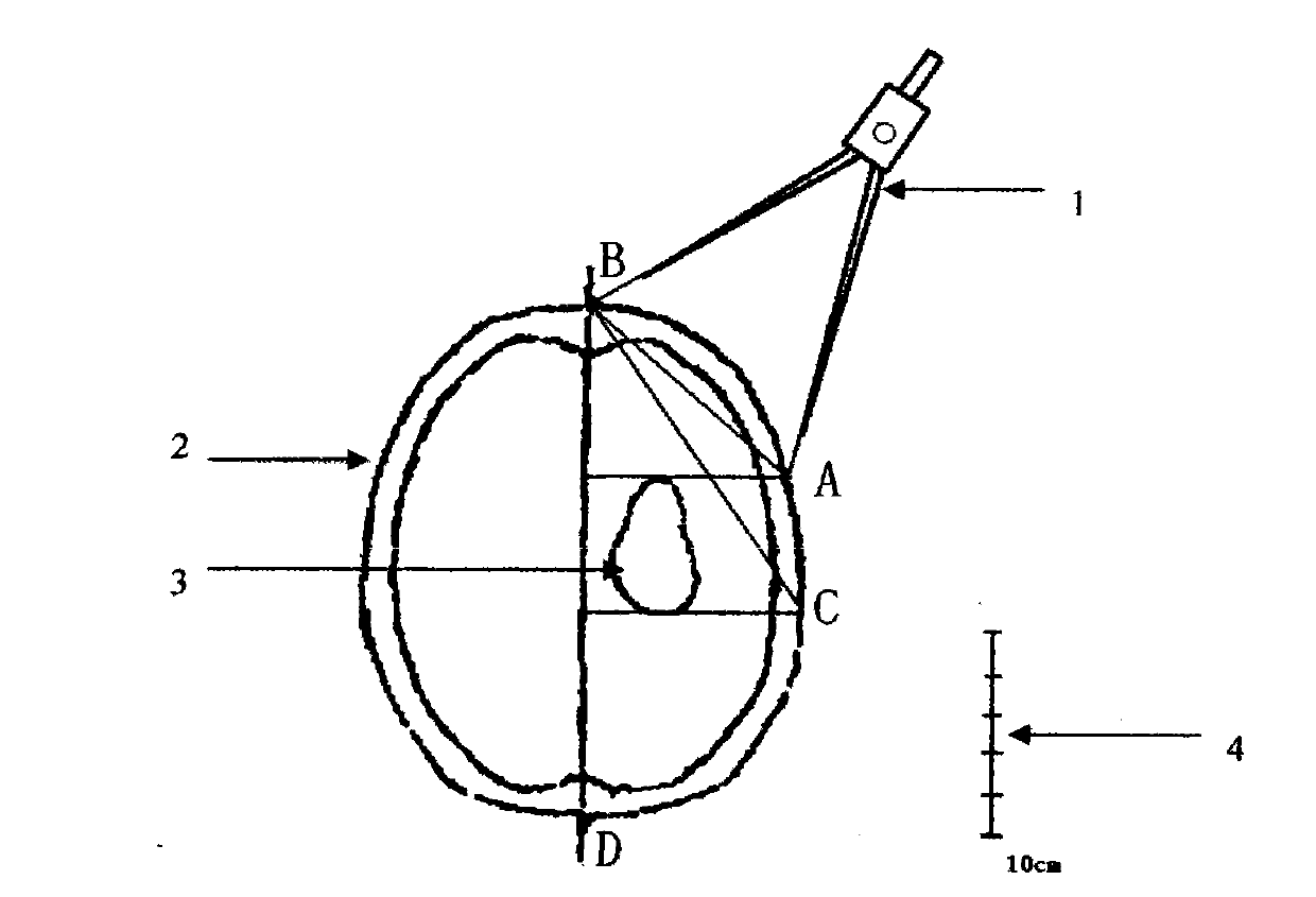
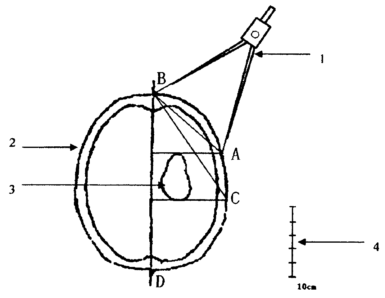
[0012] In the figure, firstly mark the intersection points B and D of the midline and the scalp on the CT axial map (2) at the largest level of the lesion, and then mark the lesion (3) the anterior and posterior boundaries after avoiding important structures and functional areas For projection points A and C, use the compass (1) to measure the BA straight-line distance and the BC straight-line distance respectively, and use the scale (4) to calculate their actual distance.

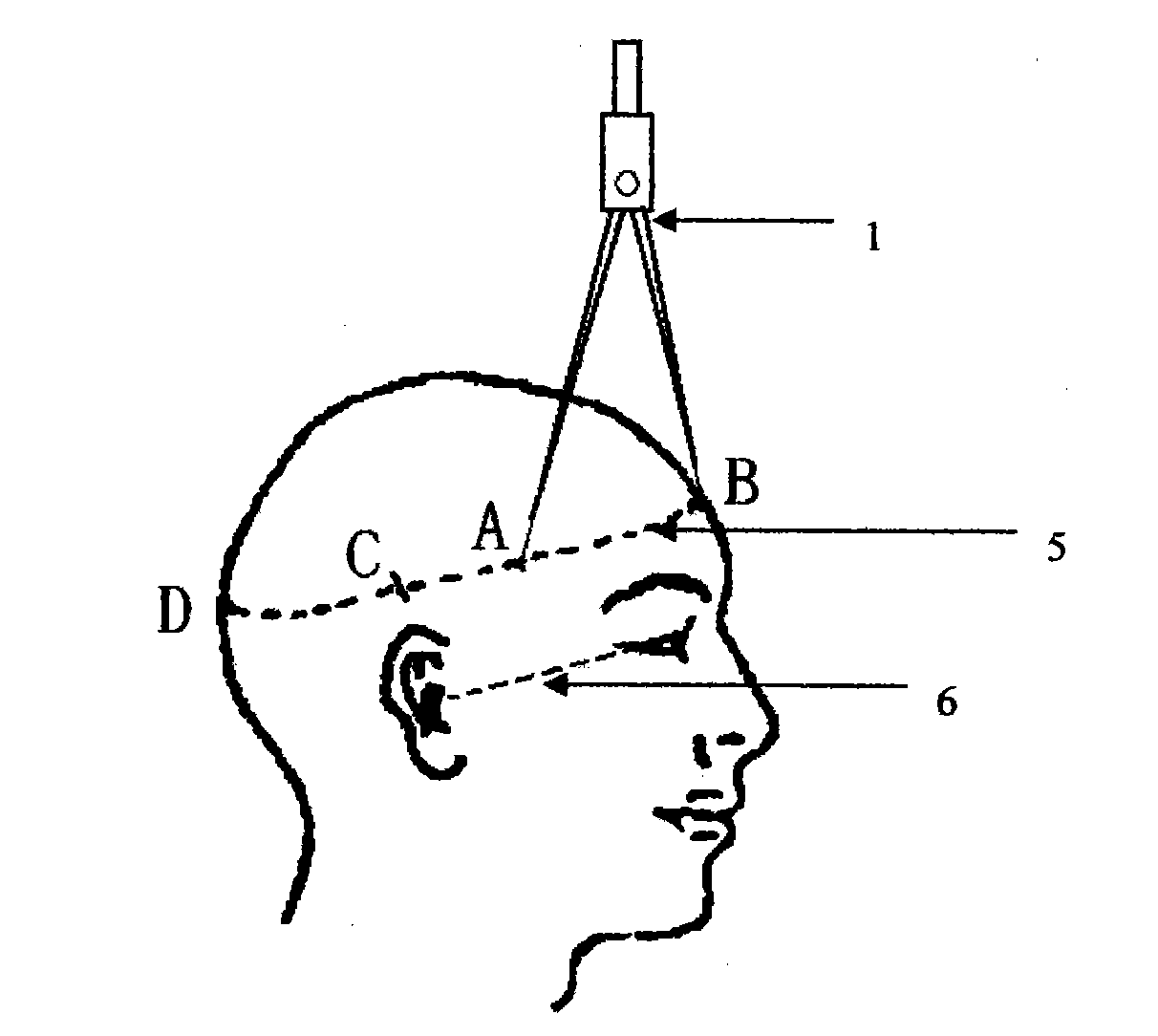
[0013] The ear canthus line (6) is selected as the baseline for head CT axial radiography, and the arc line (5) parallel to the baseline (6) is marked on the scalp body surface where the CT axial map (2) of the largest lesion range is located. Draw the midline (ie sagittal line) BD on the scalp. Use the calculated BA and BC distances to mark points A and C on the arc line (5) on the side where the lesion is located. These two points are the projection of the anterior and posterior boundary of the intracra...


PUM


Abstract

The invention discloses a simple method for performing quick and convenient body surface positioning of intracranial lesions before a neurosurgical operation. In the method, a canthomeatal line is selected as a base line in skull CT axial radiography, a CT film with the largest lesion range is selected, the distance between the intersection points of the projective point of a lesion on head skin and a central line and the head skin on the skull CT film is measured with a compasses and a ruler, and the actual distance (shown in a figure in the abstract) between the two points is worked out according to a measuring scale on the CT film; a central line (sagittal line) is marked on the head skin of the patient, a circular arc parallel to the base line is drawn on the head skin on the layer on which the measured CT film exists, and after the intersection point of the central line and the circular arc is determined, and the front and back boundaries of the lesion are marked on the circular arc with the compasses according to the length measured before; and the upper and lower boundaries of the lesion are marked in the same way. The boundaries define the projection of the lesion on the head skin. In addition, the method can be used for positioning intracranial lesions by using a skull magnetic resonance imaging (MRI) axis view, a sagittal view and a coronal view.

Description

technical field [0001] The invention relates to a body surface positioning method for intracranial lesions. Background technique [0002] During craniocerebral surgery, whether the location of intracranial lesions is accurate is critical to the success of the operation, and has a profound impact on the rehabilitation of postoperative patients and the prevention of complications. Since most of the brain lesions are located in the deep part of the brain, even small lesions located in the superficial part, it is difficult to accurately locate them with traditional surgical methods, which makes accurate resection of intracranial lesions difficult. Some intracranial lesions have unclear boundaries with the surrounding brain tissue and are difficult to identify even under a microscope. If the preoperative positioning is not accurate, it may be difficult to find during the operation. There have been many reports on intracranial lesion localization methods, such as scalp marking af...

Claims


Application Information

Patent Timeline
Patent Type & Authority Applications(China)
IPC IPC(8): A61B6/04A61B6/03
Inventor 姬西团赵东升
Owner 姬西团
Why Eureka
Try Eureka