Tee joint forming die and tee joint forming method

A technology for forming molds and tees, which is applied in the direction of manufacturing tools, broaching machines, broaching devices, etc., can solve the problems of affecting the flow rate of air-conditioning and refrigeration system pipes, thinning of product bending parts, and poor consistency of tee forming. Appearance quality, reduced product scrap rate, and good product consistency

Inactive Publication Date: 2011-09-28
李镇南
View PDF6 Cites 27 Cited by
  • Summary
  • Abstract
  • Description
  • Claims
  • Application Information

AI Technical Summary

Problems solved by technology

[0005] 2. After the straight pipe is extruded, it usually needs to be bent into a Y-shaped tee, bypass, claw and other special-shaped tees. It is easy to bend the T-shaped pipe into the required tee shape. Increased flatness of the

Method used


Image

  • Tee joint forming die and tee joint forming method
  • Tee joint forming die and tee joint forming method
  • Tee joint forming die and tee joint forming method

Examples


Embodiment 1

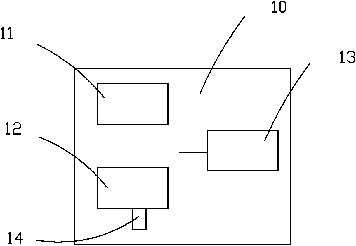
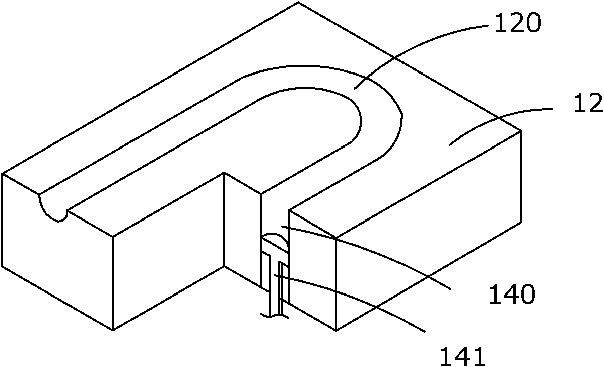
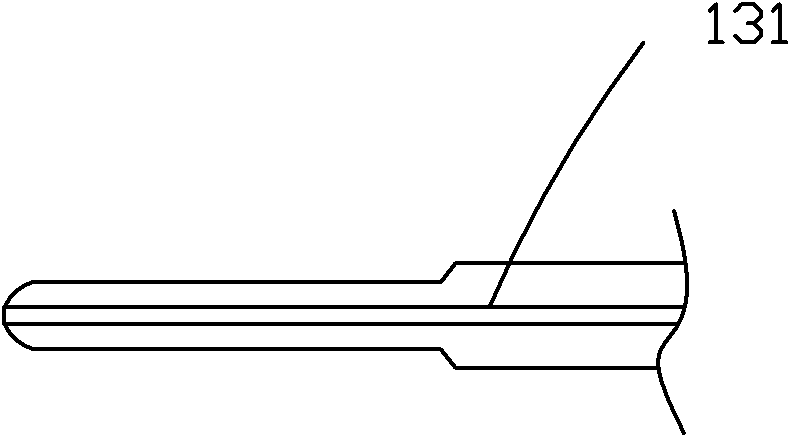
[0032] The tee forming die of the present invention is composed of an upper die 11 and a lower die 12 . See figure 1 , The three-way forming equipment also includes a hydraulic press 10, a hydraulic cylinder 13, a thimble 131, a support cylinder 14 and a control system. The upper die 11 is installed on the upper cylinder of the hydraulic press 10 and is controlled by the control system to move up and down in the vertical direction. The lower die 12 is placed on the platform of the hydraulic press. The support cylinder 14 is used to control the extrusion length of the three-way branch pipe. The function of the thimble 131 is to The two main ports of the workpiece clamped and fixed by the upper and lower molds are completely blocked, and the liquid filling process is carried out to squeeze the three-way workpiece to form the workpiece into a three-way. The thimble structure can be that one is connected to the hydraulic cylinder, and the other is a sealed entity, and the liquid ...

Embodiment 2

[0041] Figure 4 , Figure 5 It represents a three-way processing mold structure in which the direction of the branch pipe and the main pipe are perpendicular to each other. see Figure 4 , A patrix 11 is provided with a U-shaped groove group consisting of eight U-shaped grooves, and the U-shaped grooves are arranged symmetrically in two rows, so that one-time processing of three links can produce 8 pieces at the same time, greatly improving labor productivity. Each of the four corners of the upper mold has a screw 21 to fix the upper mold on the hydraulic press, and a positioning pin 22 is respectively arranged on both sides of the U-shaped groove group of the upper mold. When the lower and lower molds are closed, the positioning pins 22 of the upper mold Insert it into the positioning pin hole of the lower mold to ensure accurate clamping of the upper and lower molds. See Figure 5 , the lower mold 12 is provided with a U-shaped groove group consisting of eight U-shaped ...

Embodiment 3

[0043] Figure 6 It shows a Y-shaped tee processing mold structure in which the branch pipe and the main pipe are on the same plane, and the direction of the main pipe port and the branch pipe port is opposite. As shown in the figure, upper mold 11 is provided with three Y-shaped grooves arranged side by side. The Y-shaped grooves are composed of U-shaped grooves and a straight groove connected to the bottom of the U-shaped grooves. The structure of the lower mold is the same as that of the upper mold. When the upper and lower molds are closed, the semicircular straight grooves of the upper and lower molds surround the three-way branch lumen for processing branch pipes. When the tee is processed, the U-shaped tee workpiece is placed in the U-shaped groove of the lower mold, the upper and lower molds are closed, and multiple thimbles are inserted into the cavity formed by the U-shaped grooves of the upper and lower molds at the same time to block the hole of the tee workpiece. ...


PUM


Abstract

The invention provides a tee joint forming die. The tee joint forming die comprises an upper die and a lower die which are combined together, wherein semi-circular groove-shaped cavities for accommodating a tee joint workpiece are symmetrically arranged on the upper die and the lower die; openings of the cavity are formed on lateral sides of the upper die and the lower die; the cavity is communicated with a tee joint branch pipe cavity; a support rod capable of reciprocating displacement is arranged in the tee joint branch pipe cavity; the support rod is connected with a support cylinder and transfers pressure by the support cylinder; and a tee joint branch pipe is filled with medium in the tee joint workpiece, and is formed in the tee joint branch pipe cavity in the hydraulic action of a hydraulic cylinder. By the tee joint forming die, a tee joint finished product has higher appearance quality and excellent uniformity; the U-shaped bend of the tee joint has smooth transition, the outer diameter of each position of the tee joint can achieve the requirement of equal diameter; and the current problem that the bend is flat after lead is filled can be solved.

Description

technical field [0001] The invention relates to the field of mold processing, and more specifically relates to a tee forming mold and a tee forming method. Background technique [0002] A tee is a pipe connection. Also known as pipe fittings tee, tee fittings or tee joints, the tee is used at the main branch of the main pipeline. It has a wide range of uses, a wide range of industries, and a wide range of applications. Tees made of copper are common in the field of refrigeration. The traditional method of making copper tees is mainly the lead filling method. The copper pipe is cut to a certain length, and the melted lead is poured into the inner cavity of the copper pipe. After the inner cavity of the tube is solidified, remove the lead adhering to the surface of the copper tube and the lead at the nozzle of the copper tube. A small hole is drilled and the copper pipe is extruded into a copper pipe tee through a hydraulic press. After the tee is formed, it needs to be hea...

Claims


Application Information

Patent Timeline
IPC IPC(8): B21D26/033B23D37/10
Inventor 李镇南
Owner 李镇南
Why Eureka
Try Eureka