

Walking type incremental launching device and bridge incremental launching construction method using same
A jacking device and walking-type technology, which is applied to bridge construction equipment and its bridge construction field, can solve problems such as cost increase, and achieve the effects of reducing bridge construction cost, facilitating monitoring and control, and reasonable stress on the overall structure
- Summary
- Abstract
- Description
- Claims
- Application Information
AI Technical Summary
Problems solved by technology
Method used
Image

Examples
Embodiment 1
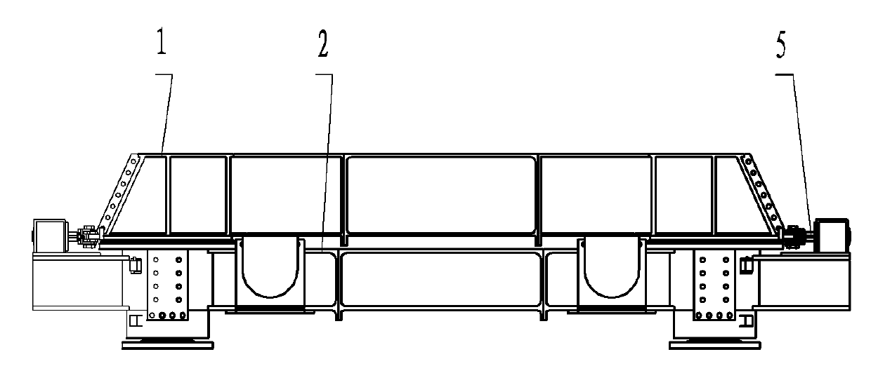
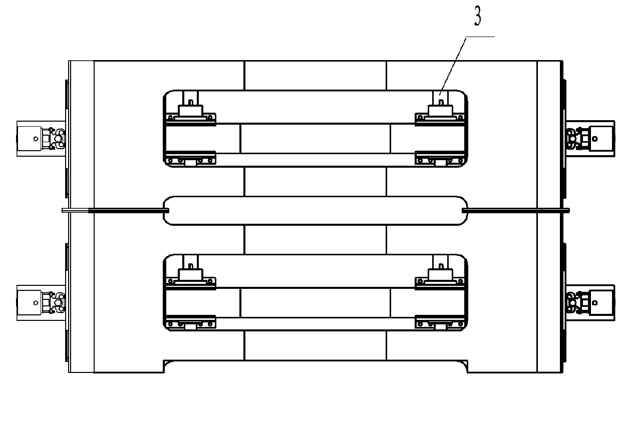
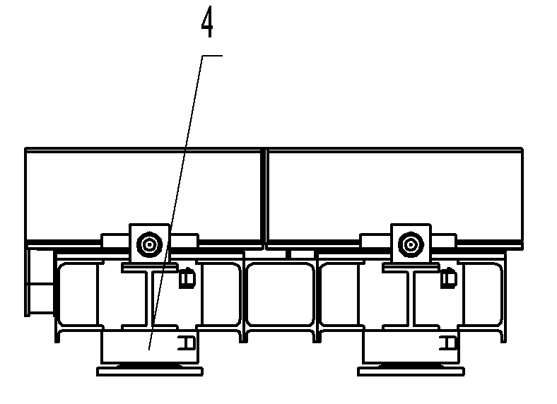
[0016] Embodiment one: a kind of walking type pushing device, such as Figure 1-1 to Figure 1-4 As shown, the walking pusher includes five parts: a slide box 1, a slideway 2, a translation jack 3, a lifting jack 4, and a deviation correction jack assembly 5.
[0017] Described slide box 1 is a quadrilateral carrier, is made up of 4 identical slide box main units 11 and 2 transverse slide box main body connectors 121 that connect slide box main unit 11 that are positioned at frame 4 corners (referring to Figure 2-1 to Figure 2-4 ); Described each slide box main body unit 11 comprises slide box main body steel structure 111, stainless steel plate 112, push away ear 113 and translation guide plate 114, the slide box main body steel structure 111 of slide box main body unit 11 is made of 4 hollow A hollow steel frame assembled by the frame includes a load-bearing part 111a composed of a right-angled trapezoidal cross-section and a rectangular hollow frame with a cross-section, and...
Embodiment 2
[0025] Embodiment two: a kind of method for bridge jacking construction---install the walking type jacking method of bridge girder section, it is to utilize the walking type jacking device described in embodiment one of the present invention, to bridge girder section (this implementation For example, a steel box girder) is assembled in sections and pushed into place as a whole, which includes the following steps (see Figure 9-1 to Figure 9-5 ): A, install pusher VI (referring to Figure 9-1 ): Assemble the jacking device VI and pad beam I on the jacking device installation platform VII of the bridge pier; B, jacking the steel box girder II (see Figure 9-2 ): The jacking jack IV extends the cylinder to the set stroke through the control system, and lifts the entire pushing device and the steel box girder II, leaving a certain distance away from the pad beam I; C. The steel box girder II is pushed forward (see Figure 9-3 ); Synchronously control the extension cylinder of the...
PUM
 Abstract
Description
Claims
Application Information