Maximum power point detection tracking method and circuit of power generating device

A technology of maximum power point and power generation device, applied in the direction of adjusting electrical variables, control/regulation systems, instruments, etc., can solve the problems of complex realization process, maximum power point oscillation, small application range, etc., and achieve fast locking speed and long locking time Short, Simple Effects

Inactive Publication Date: 2011-09-28
KUNMING UNIV OF SCI & TECH
View PDF5 Cites 12 Cited by
  • Summary
  • Abstract
  • Description
  • Claims
  • Application Information

AI Technical Summary

Problems solved by technology

[0004] In order to solve the problems of the above-mentioned maximum power point detection and tracking method of a power generation device such as small applicable range, maximum

Method used


Image

  • Maximum power point detection tracking method and circuit of power generating device
  • Maximum power point detection tracking method and circuit of power generating device
  • Maximum power point detection tracking method and circuit of power generating device

Examples


Embodiment 1

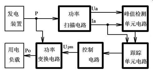
[0027] Such as image 3 As shown, the maximum power point detection and tracking circuit of the power generation device of the present invention includes a power scanning circuit, a peak detection unit circuit, and a tracking unit circuit. The power scanning circuit has been described above, and will not be repeated here; the peak detection unit circuit is composed of an analog multiplication circuit, a differential circuit and a single-limit comparison circuit; the tracking unit circuit is composed of a pulse shaping circuit and a memory circuit. The connection relationship of the whole circuit is as follows: the power output terminal P of the power generation device is connected to the input terminal of the power scanning circuit, and the two input terminals of the analog multiplication circuit are respectively connected to the scanning voltage value output terminal and the scanning current value output terminal of the power scanning circuit , the output terminal of the anal...

Embodiment 2

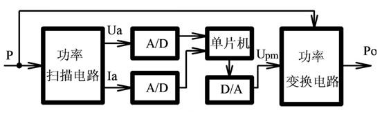
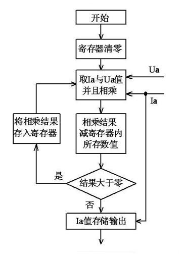
[0048] Such as Figure 4 As shown, the maximum power point detection and tracking circuit of the power generation device of the present invention includes a power scanning circuit, a peak detection unit circuit, and a tracking unit circuit. The power scanning circuit has been described above, and will not be repeated here; the peak detection unit circuit is composed of two A / D converters, a single-chip microcomputer and corresponding software modules; the tracking unit circuit is composed of a single-chip microcomputer and corresponding software modules. The connection relationship of the whole circuit is as follows: the power output terminal P of the power generation device is connected to the input terminal of the power scanning circuit, and the scanning voltage value output terminal and the scanning current value output terminal of the power scanning circuit are respectively connected to the signal input terminals of two A / D converters , the signal output terminals of the t...


PUM


Abstract

The invention relates to a maximum power point detection tracking method and circuit, in particular to a maximum power point detection tracking method and circuit of a power generating device. The maximum power point detection tracking method of the power generating device mainly comprises the following steps of: within a determined energy absorbing conversion period, taking 0.1%-1% of time of the energy absorbing conversion period to scan an output current and an output voltage of the power generating device; detecting a peak value of a power value; and locking a scanning current value corresponding to the detected maximum power point in a memorized way. The maximum power point detection tracking circuit of the power generating device, provided by the invention, comprises a power scanning circuit, a peak value detecting unit circuit and a tracking unit circuit. By using the maximum power point detection tracking method and circuit of the power generating device, provided by the invention, the maximum power points of the various power generating devices can be detected and tracked; and the method and circuit have the advantages of simple structure, short locking time, no maximum power point vibration problem and the like.

Description

technical field [0001] The invention relates to a method for detecting and tracking a maximum power point and a circuit thereof, in particular to a method for detecting and tracking a maximum power point of a power generating device and a circuit thereof. Background technique [0002] In solar energy, wind energy, wave energy and other power generation devices, since the external energy input to the power generation device is unstable, and the power generation device has internal resistance, the energy conversion efficiency of the device will closely match the impedance between the loads. relevant. The most typical example is that when the device charges the battery or supplies power to the grid, if the characteristics of the two do not match, at this time, although the power generation device can also generate power and supply power to the load, the energy conversion and utilization efficiency will not be optimal for a long time. Operating value, which directly affects the...

Claims


Application Information

Patent Timeline
IPC IPC(8): G05F1/67
Inventor 卢诚张明宇聂俊飞
Owner KUNMING UNIV OF SCI & TECH
Why Eureka
Try Eureka