Method for injecting harmonic voltage to restrain harmonic current of PMSM (permanent magnet synchronous motor)

A permanent magnet synchronous motor, harmonic voltage technology, applied in the direction of motor generator control, electronic commutation motor control, single motor speed/torque control, etc., can solve false compensation, complex single compensation mode, harmonic current suppression Problems such as unsatisfactory effect

Inactive Publication Date: 2011-09-28
CHONGQING UNIV
View PDF5 Cites 67 Cited by
  • Summary
  • Abstract
  • Description
  • Claims
  • Application Information

AI Technical Summary

Problems solved by technology

[0007] Documents (1) and (2) mainly optimize the design of the motor body and improve the sine degree of the air gap magnetic field distribution to suppress the harmonic current components caused by the motor air gap magnetic field distortion, especially the larger 5th and 7th harmonics Current components, but cannot suppress harmonic currents caused by nonlinear characteristics such as dead time of inverter switching devices, tube voltage drop, etc.
[0008] Documents (3) and (4) mainly use the method of current feedback voltage compensation to suppress the harmonic current components caused by the inherent characteristics of the inverter switching devices and the dead time, especially the larger 5th and 7th harmonics However, it cannot suppress the harmonic current caused by t...

Method used


Image

  • Method for injecting harmonic voltage to restrain harmonic current of PMSM (permanent magnet synchronous motor)
  • Method for injecting harmonic voltage to restrain harmonic current of PMSM (permanent magnet synchronous motor)
  • Method for injecting harmonic voltage to restrain harmonic current of PMSM (permanent magnet synchronous motor)

Examples


Embodiment Construction

[0046] The present invention will be further described below in conjunction with the accompanying drawings and specific embodiments.

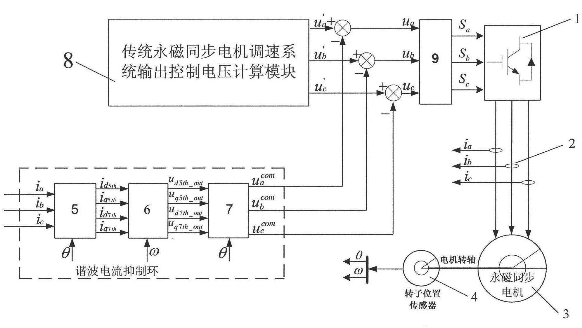
[0047] A control method for injecting harmonic voltage to suppress harmonic current of a permanent magnet synchronous motor, which includes a control object permanent magnet synchronous motor 3, a two-level voltage type PWM inverter 1 connected to the stator of the permanent magnet synchronous motor, used for three The current Hall sensor 2 for phase stator current detection, the rotor position sensor 4 for detecting the rotor position of the permanent magnet synchronous motor, and the control loop for controlling the permanent magnet synchronous motor, wherein: the control loop includes the 5th and 7th harmonic current extraction modules 5, 5th, 7th harmonic current suppression algorithm module 6, harmonic voltage dq / abc conversion module 7, traditional permanent magnet synchronous motor speed control system output control voltage calculation m...


PUM


Abstract

The invention provides a method for injecting a harmonic voltage to restrain a harmonic current of a PMSM (permanent magnet synchronous motor), which is characterized in that a ring to restrain the harmonic current is added to realize the closed-loop control for the harmonic current on the basis of extracting harmonic current components in the PMSM in real time, thus calculating to obtain harmonic voltage components which are required to be injected to restrain 5-order and 7-order harmonic currents of the PMSM; and then the obtained harmonic voltage components are injected into a three-phase control voltage in a speed control system of the PMSM so as to offset the 5-order and 7-order harmonic components in a motor current when the PMSM runs, thereby reaching the purpose of restraining the 5-order and 7-order harmonic currents. The method is used to solve the technical difficulty that current ZCP (zero crossing point) is required to detect accurately in a traditional mode to restrain the harmonic current, remarkably improves the current waveform of the motor, effectively restrains the 5-order and 7-order harmonic currents caused by the nonlinear characteristics of an inverter and the air-gap field distortion of the motor, effectively reduces the additional loss caused by the 5-order and 7-order harmonic current components, reduces the electromagnetic torque and the revolving speed pulse of the PMSM and improves the running efficiency and the running reliability of the PMSM.

Description

technical field [0001] The invention belongs to the field of harmonic current control of permanent magnet synchronous motors, in particular to a control method for suppressing the harmonic current of permanent magnet synchronous motors by injecting harmonic voltage. Background technique [0002] In the steady state operation of permanent magnet synchronous motor (PMSM), nonlinear characteristics such as dead time of inverter switching device, tube voltage drop, etc., or cogging effect, winding distribution form, magnetic circuit magnetic saturation effect, rotor pole structure, etc. The air gap magnetic field distortion caused will cause the motor current waveform to be distorted, so that the motor current contains a series of harmonic components such as 5th, 7th, 11th, and 13th orders. These harmonic current components, especially the 5th and 7th harmonic current components with a large proportion, will not only generate additional losses in the stator winding and iron core...

Claims


Application Information

Patent Timeline
IPC IPC(8): H02P6/08H02P6/16H02P21/14H02J3/01
CPCY02E40/40Y02P80/10
Inventor 廖勇刘刃姚骏黄嵩
Owner CHONGQING UNIV
Why Eureka
Try Eureka