
Heating device

A technology of heating device and heating tank, which is applied in the direction of textiles and papermaking, etc., to achieve the effect of favorable space utilization and low consumption

Inactive Publication Date: 2013-08-21
OERLIKON TEXTILE GMBH & CO KG
View PDF5 Cites 0 Cited by
  • Summary
  • Abstract
  • Description
  • Claims
  • Application Information

AI Technical Summary

Problems solved by technology

This enables a compact arrangement of the inner heating channels in the heating device, but also has the disadvantage that separate heating devices are required for the crimping section and the relaxation section

Method used


Image

  • Heating device
  • Heating device
  • Heating device

Examples


Embodiment Construction

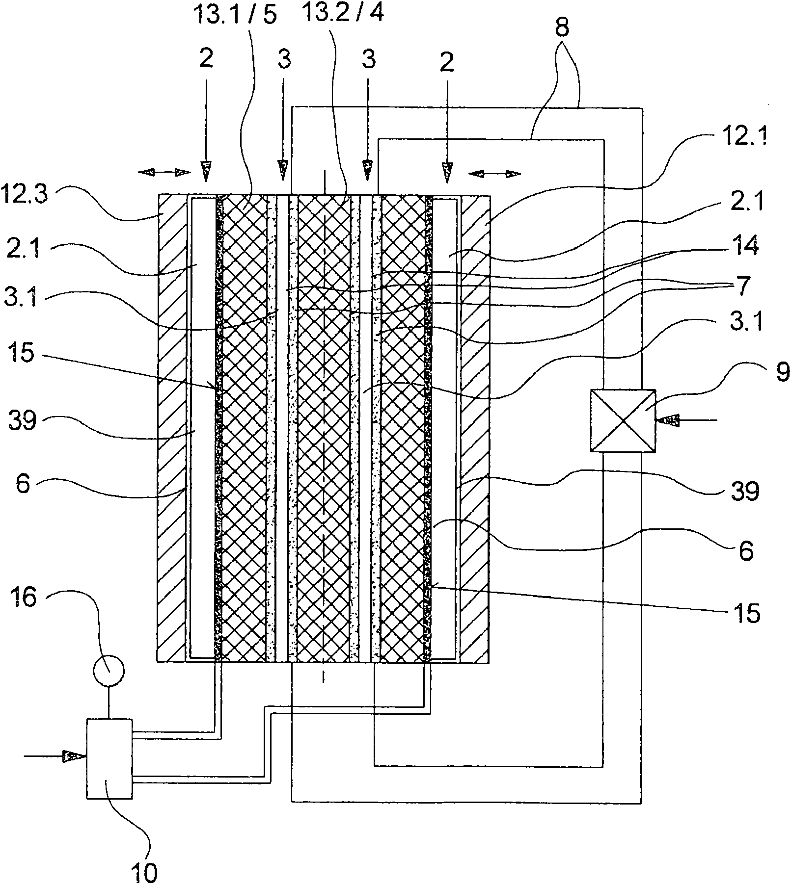
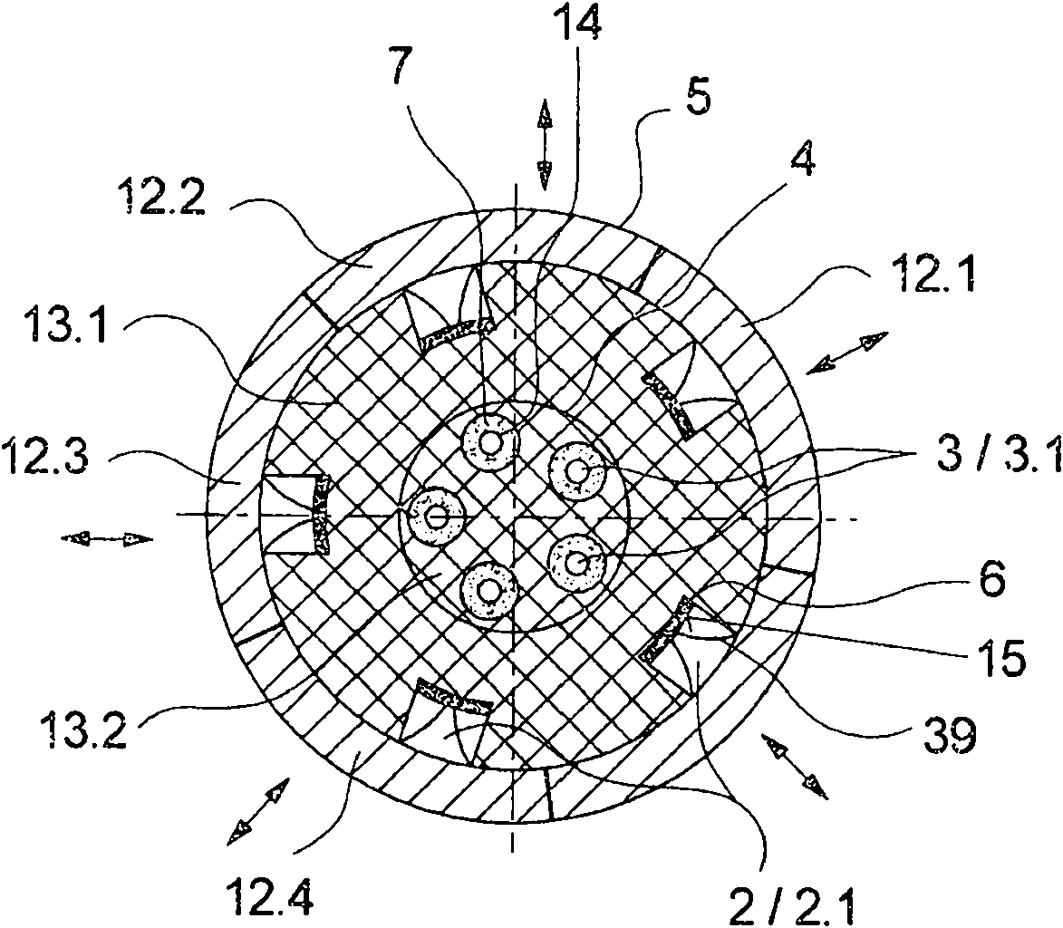
[0033] figure 1 shows a schematic longitudinal sectional view of a first embodiment of a heating device according to the invention, while figure 2 A cross-sectional view is shown. If there is no explicit reference to one of the figures, the following description applies to both figures.

[0034] The heating device has a plurality of heated heating channels 2.1 and 3.1. The heating channels 2.1 and 3.1 are divided into two heating groups 2 and 3 . The heating channels 2.1 of the heating group 2 are formed in the edge region 5 of the heating device. The individual heating channels 3 . 1 of the heating group 3 are arranged in the central region 4 , they are located concentrically in the center of the edge region 5 and are surrounded by the edge region 5 . The heating channels 2.1 of the heating group 2 are arranged concentrically with the heating channels 3.1 of the heating group 3 and surround them. In this exemplary embodiment, the heating group 2 consists of a total of f...


PUM


Abstract

The invention relates to a heating device for threads, particularly for use in a texturing machine, comprising several elongated heating channels, which are divided into two heating groups. The threads can be heated within a texturing section by the heating channels of one of the heating groups and in a downstream relaxation section by the heating channels of the second heating group. According to the invention, in order to obtain a compact and energy-efficient arrangement of the heating channels, the heating channels are held in a concentric cross-sectional arrangement in such a way that a first heating group of the heating channels lies in a central zone and a second heating group of the heating channels lies in an outer zone enclosing the central zone.

Description

technical field [0001] The invention relates to a heating device for yarn, in particular in a texturing machine, and to a texturing machine. Background technique [0002] It is known in the manufacture of synthetic textile threads that, after melt spinning, the synthetic yarns are treated by a texturing process in order to obtain the desired structure for textile applications. In particular, multi-fiber yarns are texturized, stretched and relaxed here. To carry out this treatment phase, it is known to subject the yarn to a first heat treatment in the texturing section and to subject it to a second heat treatment in the relaxation section. For this purpose, a plurality of individual heating devices are usually used, which are arranged one behind the other in the yarn flow. [0003] In order to be able to carry out such a heat treatment as energy-efficient as possible during the texturing process, heating devices with two separate heating groups formed by elongated heating c...

Claims


Application Information

Patent Timeline
Patent Type & Authority Patents(China)
IPC IPC(8): D02J13/00D02G1/02
CPCD02J13/001D02G1/0266
Inventor K·巴特科维阿克D·奥伯施特拉斯M·菲舍尔H-G·施罗德S·康拉德J·席佩尔
Owner OERLIKON TEXTILE GMBH & CO KG
Learn More