
Heat pipe and electronic device

A technology of heat pipes and heating elements, which is applied in the direction of circuits, electrical components, and electric solid devices, can solve the problems of low cooling capacity, insufficient cooling capacity of heat pipes and cooling systems, and low thermal diffusion capacity from end parts to heat conduction elements, etc., to achieve Keep cool effect

Inactive Publication Date: 2011-09-28
莫列斯日本有限公司 +1
View PDF7 Cites 4 Cited by
  • Summary
  • Abstract
  • Description
  • Claims
  • Application Information

AI Technical Summary

Problems solved by technology

However, there is the problem that the light-emitting elements are hidden behind components of the cooling system
However, in the cooling system disclosed in the '808 patent, there are problems in that the heat diffusivity from the end portion to the heat conduction member is low, and the cooling capacity is low in the case where the light emitting element is arranged in the end portion.
In other words, even though it is intended to arrange the light emitting element in the end portion of the heat receiving portion to reduce the installation volume, the cooling capacity in the conventional heat pipe and cooling system is insufficient
[0008] In addition, since light emitting elements are generally compact and a plurality of light emitting elements are arranged compared with semiconductor integrated circuits, there is a problem that it is difficult to arrange light emitting elements near the center of the heat receiving portion
Because the diffusion direction and the return direction of the cooling medium contained in the circuit board are unidirectional, it is difficult for the evaporated cooling medium to be cooled sufficiently, and drying out will occur

Method used


Image

  • Heat pipe and electronic device
  • Heat pipe and electronic device
  • Heat pipe and electronic device

Examples


Embodiment approach 1

[0055] Embodiment 1——Description of the concept of heat pipe

[0056] First, an explanation will be given of the concept of a heat pipe.

[0057] The heat pipe is configured such that a cooling medium is sealed in the inner portion, and a surface forming a heat receiving surface is in contact with a heating element including an electronic part. The internal cooling medium is evaporated by receiving heat from the heating element, and absorbs heat from the heating element while evaporating. The evaporated cooling medium moves (is diffused) in the heat pipe. The heat of the heating element is transferred due to this movement. The moving evaporated cooling medium is cooled in the heat dissipating surfaces of the heat pipes or the like (or by auxiliary cooling means such as heat sinks, cooling fans, etc.), thereby being condensed. The cooling medium that is condensed to become liquid flows back into the inner portion of the heat pipe to move to the heat receiving surface again...

Embodiment approach 2

[0160] Next, a description will be given of Embodiment Mode 2.

[0161] In Embodiment Mode 2, a description will be given of the experimental results regarding the superiority of the heat pipe 1 .

[0162] The inventors conducted experiments as to what shape is optimal for the vapor diffusion path 6 and the capillary flow path 7 provided in the heat pipe 1 .

Embodiment 1

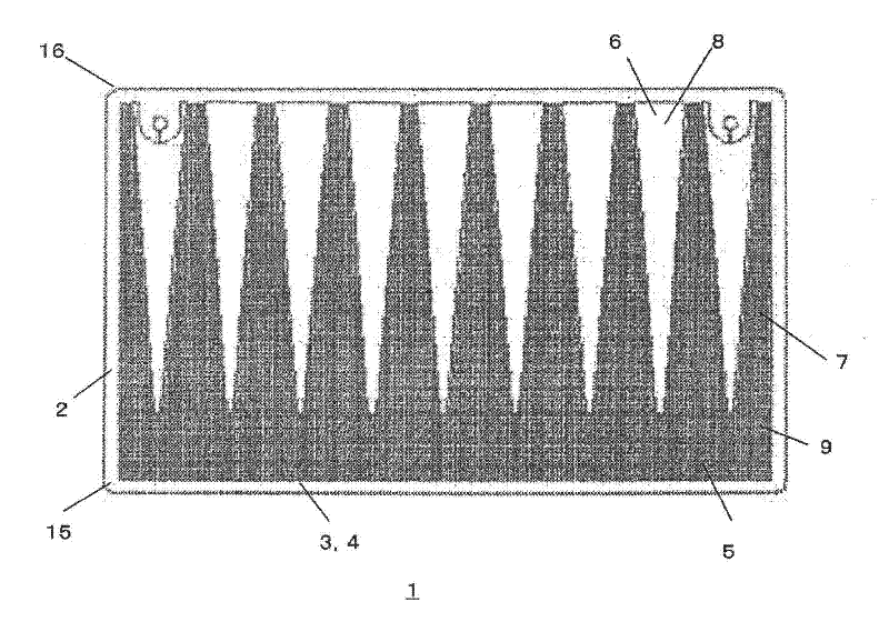
[0165] The heat pipe 40 according to Embodiment 1 is provided with a vapor diffusion path 6 and a corresponding capillary flow path 7 (in the capillary flow path 7, the width gradually narrows from the first end portion 15 to the second end portion 16), where the vapor The width in the diffusion path 6 gradually narrows from the first end portion 15 to the second end portion 16 .


PUM


Abstract

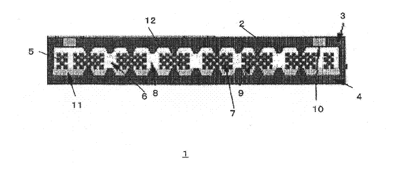
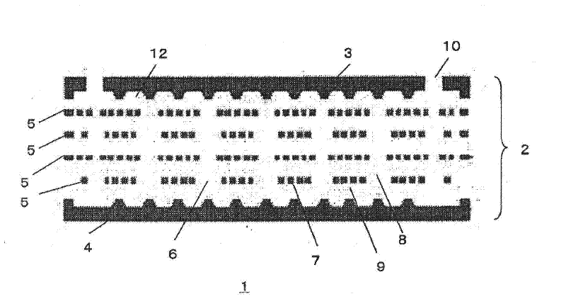
The Present Invention provides a heat pipe and an electronic device which can efficiently cool a light emitting element arranged in an end portion, so that it is possible to efficiently mount the heat pipe in a narrow space. The heat pipe is provided with an upper plate (3), a lower plate (4) opposing the upper plate (3), one intermediate plate or a plurality of intermediate plates (5) laminated between the upper plate (3) and the lower plate (4), a main body portion (2) formed by lamination of the upper plate (3), the lower plate (4) and the intermediate plate (5) and capable of sealing a cooling medium, a vapor diffusion path (6) capable of diffusing a vaporized cooling medium, and a capillary flow path (7) capable of reflowing a condensed cooling medium, and the vapor diffusion path (6) is formed from a first end portion (15); of the main body portion toward a second end portion (16) opposing the first end portion (15).

Description

technical field [0001] The present invention relates generally to heat pipes, and more particularly, the present invention relates to heat pipes for cooling heating elements. Background technique [0002] In electronic devices, electronic components are usually configured as heating elements that generate heat by an electric current flowing inside. If the heat generation of the heating element reaches a fixed temperature or higher, there is a problem that operation cannot be ensured, thereby adversely affecting other parts of the electronic device, and may adversely affect the casing. As a result, performance degradation of the electronic device may result. [0003] Various proposals have been made to cool the heating element, eg heat pipes cooled by sealing the evaporation and condensation of the cooling medium. In this embodiment, the heat pipe transfers heat from the heating element to the cooling medium, which evaporates on contact with the heat, thereby dissipating he...

Claims


Application Information

Patent Timeline
Patent Type & Authority Applications(China)
IPC IPC(8): H01L23/427F28D15/02F28D15/04
CPCH01L2924/0002F28D15/046H01L23/427F28D15/0233H01L2924/00F28D15/02F28D15/04H05K7/20
Inventor 鹤田克也福永伦康小谷俊明水田敬
Owner 莫列斯日本有限公司
Learn More