

Moving-magnet loudspeaker and method for manufacturing same
A loudspeaker and moving magnet technology, applied in the field of moving magnet loudspeakers and their manufacturing, can solve the problems of difficulty in realizing a compact and thin moving magnet loudspeaker, and reduce efficiency, so as to reduce inductance, improve efficiency, and maintain magnetic flux density. Effect
- Summary
- Abstract
- Description
- Claims
- Application Information
AI Technical Summary
Problems solved by technology
Method used
Image


Examples
Embodiment Construction
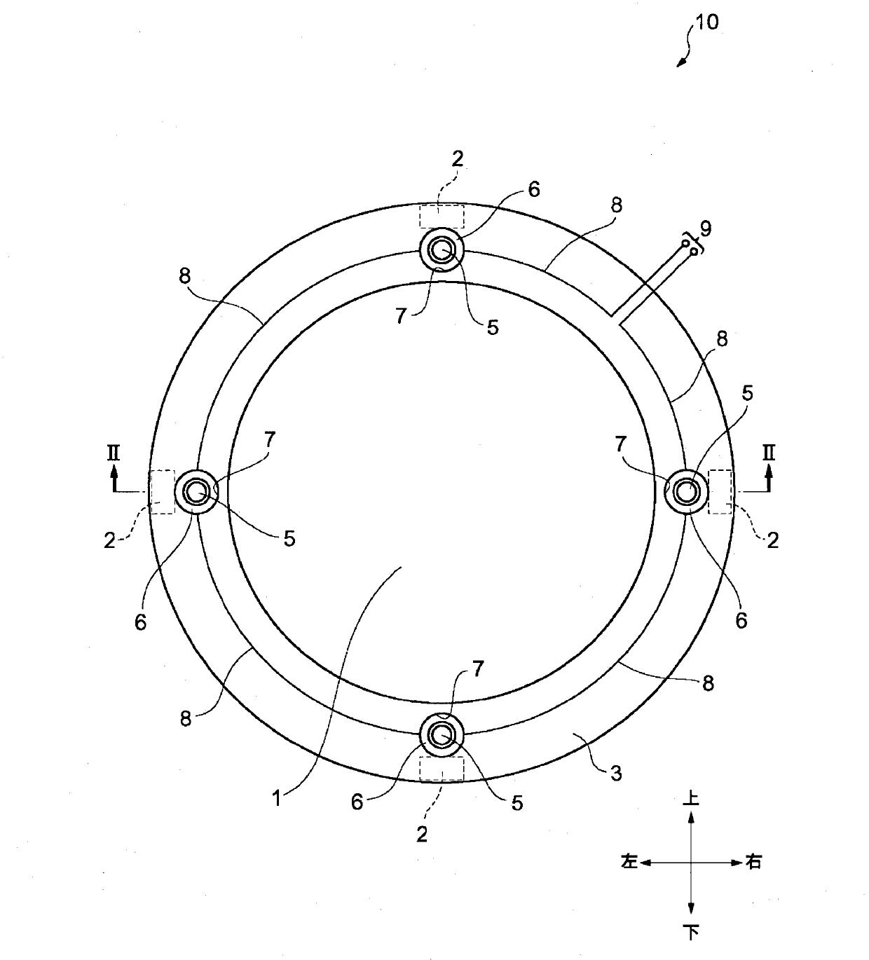
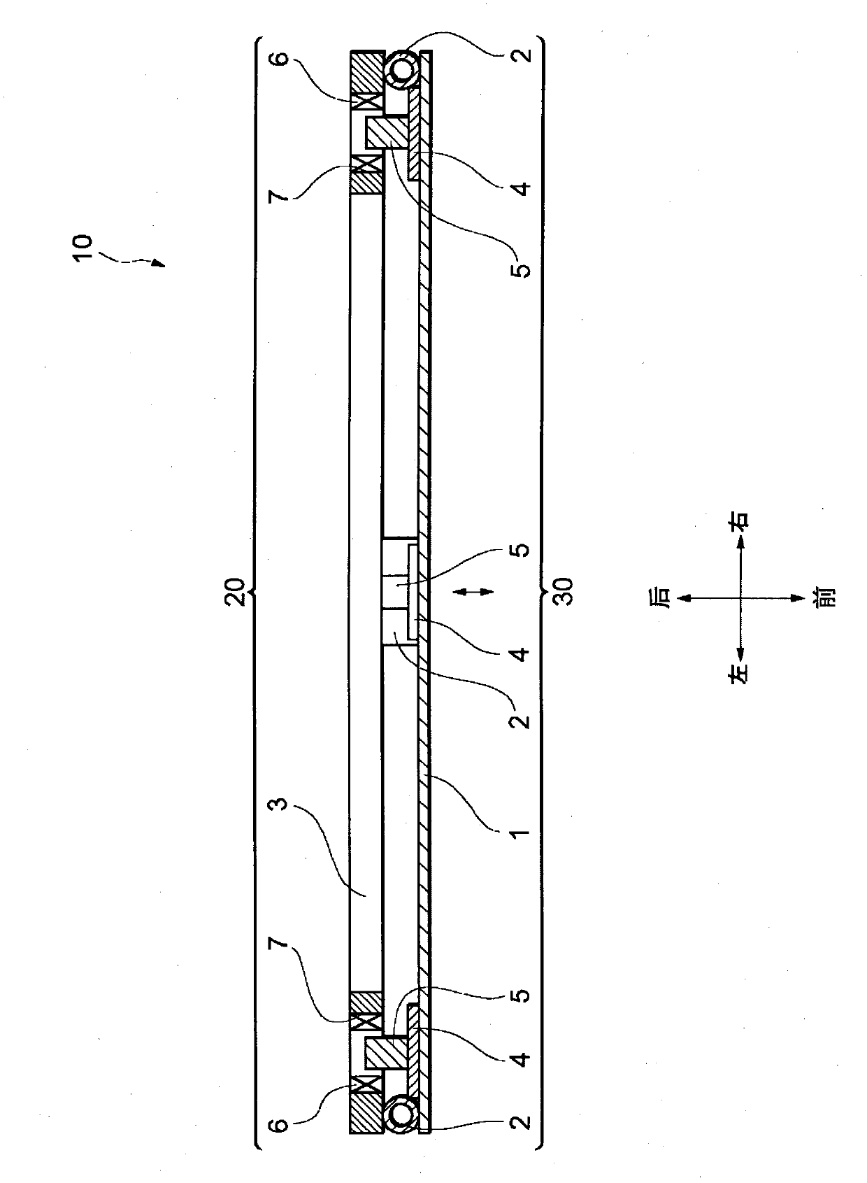
[0059] Next, a moving magnet speaker 10 according to a first embodiment of the present invention will be described with reference to the drawings. For convenience of description, the arrow directions shown in the drawings are defined as front and rear, left and right, and up and down.
[0060] First, refer to figure 1 and figure 2 The structure of the moving magnet speaker 10 will be described. The moving magnet loudspeaker 10 described below is an example in which the present invention is applicable to a full-range speaker, that is, a full-range speaker, but the present invention is not limited thereto, and may also be applicable to a high-frequency range, that is, a high-frequency speaker, or to a low-frequency range, that is, a high-frequency speaker. woofer.
[0061] The moving magnet speaker 10 has an annular fixed support portion 20 and a disk-shaped vibrating portion 30 attached to the front side of the fixed support portion 20 . Furthermore, the shapes of the fixe...
PUM
 Abstract
Description
Claims
Application Information