
Flat plate heat pipe and manufacturing method thereof

A flat-plate heat pipe and manufacturing method technology, applied in heat exchange equipment, indirect heat exchangers, lighting and heating equipment, etc., can solve problems such as easy to fall off, difficult to control the height of the support body, and difficult to assemble

Inactive Publication Date: 2011-10-05
FU ZHUN PRECISION IND SHENZHEN +1
View PDF8 Cites 12 Cited by
  • Summary
  • Abstract
  • Description
  • Claims
  • Application Information

AI Technical Summary

Problems solved by technology

The main problems of using this kind of support body are as follows: because the two ends of the support body usually need to be chamfered, it is troublesome to manufacture; and this kind of support body is directional, and it is difficult to assemble it with the sintering mold before the capillary structure is sintered, which consumes manpower; The height tolerance of the support body is difficult to control, which usually leads to poor sintering bonding force between some support bodies and the metal shell, and it is easy to fall off in the subsequent process

Method used


Image

  • Flat plate heat pipe and manufacturing method thereof
  • Flat plate heat pipe and manufacturing method thereof
  • Flat plate heat pipe and manufacturing method thereof

Examples


Embodiment Construction

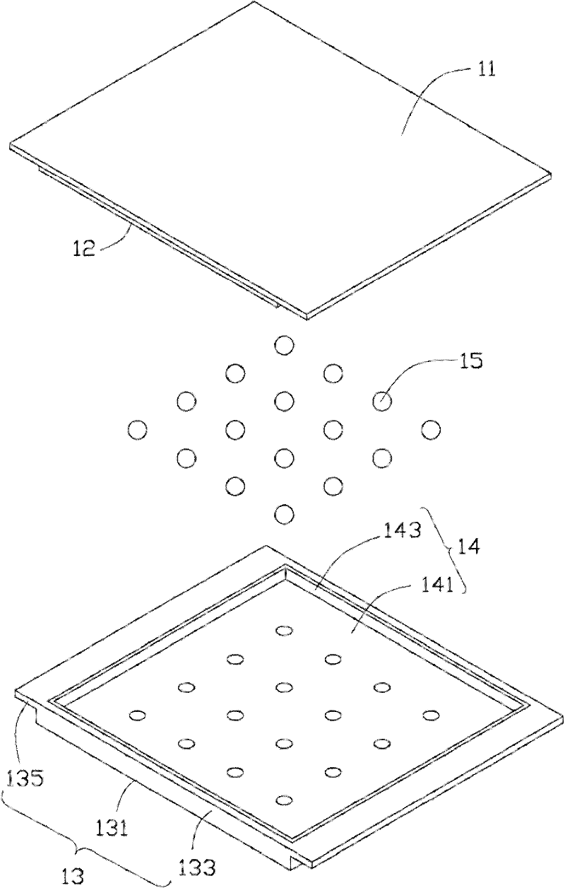
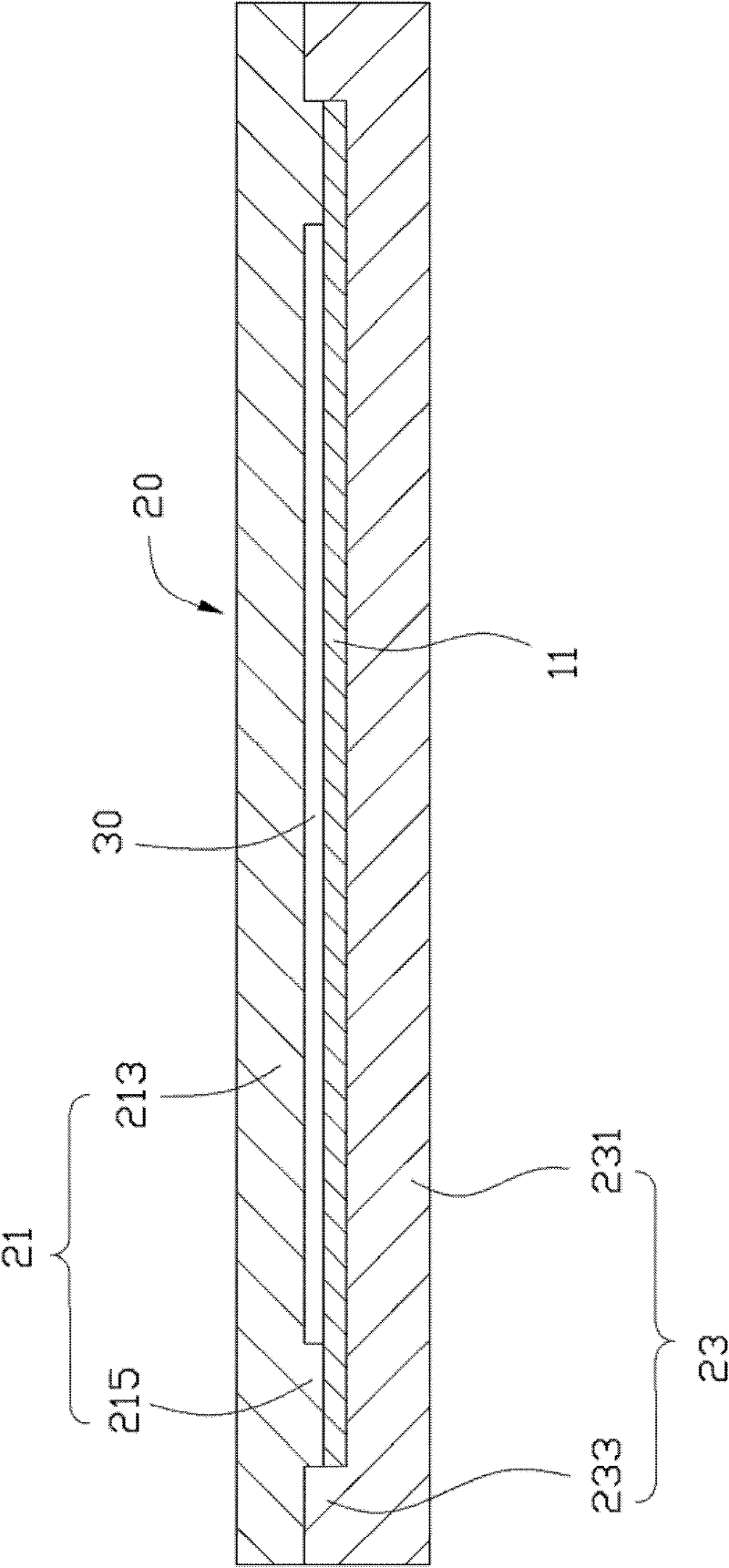
[0015] The manufacturing method of the flat heat pipe in one embodiment of the present invention includes the following steps: providing a first metal sheet body; providing several spherical supports and a second metal sheet body, the second metal sheet body includes a bottom plate and a The side plate extending from the bottom plate; placing the spherical support on the bottom plate of the second metal sheet; closing the first and second metal sheets, and performing diffusion welding on them, so that the first and second metal sheets are sealed and connected , and make the spherical support body sandwiched between the bottom plates of the first metal sheet body and the second metal sheet body and directly abut against the bottom plates of the first metal sheet body and the second metal sheet body.

[0016] see figure 1 and figure 2 , the manufacturing method of the above-mentioned heat pipe will now be described in detail by taking the manufacturing process of a flat heat p...


PUM


Abstract

The invention relates to a manufacturing method of a flat plate heat pipe. The manufacturing method comprises the following steps of: providing a first metal sheet body; providing a plurality of spherical supporting bodies and a second metal sheet body, wherein the second metal sheet body comprises a base plate and a side plate extending from the base plate; arranging the spherical supporting bodies on the base plate of the second metal sheet; and folding the first metal sheet body and the second metal sheet body, and performing diffusion welding on the first metal sheet body and the second metal sheet body so that the first metal sheet body and the second metal sheet body are in sealing connection with each other, and the spherical supporting bodies are clamped between the first metal sheet body and the base plate of the second metal sheet body and directly pressed against the first metal sheet body and the base plate of the second metal sheet body. The flat plate heat pipe comprises a flat plate shell which comprises a base plate and a top plate opposite to the base plate; and at least one spherical supporting body is clamped between the base plate and the top plate. The supporting bodies in the invention are spherical, easy to manufacture and free of direction, can be conveniently arranged in the shell and easily combined with the shell without falling, so the flat plate heat pipe has stable performance.

Description

technical field [0001] The invention relates to a heat pipe and a manufacturing method thereof, in particular to a flat heat pipe and a manufacturing method thereof. Background technique [0002] With the continuous development of the electronic information industry, the integration of electronic products is getting higher and higher, and the heat emitted by the electronic components in it is also increasing. The industry usually uses flat heat pipes for heat dissipation of electronic components. This flat heat pipe usually includes a metal shell, a capillary structure attached to the inner surface of the metal shell, a supporting body supporting the metal shell, and an appropriate amount of working medium injected into the metal shell. The current mainstream supports are cylindrical metal rods. The main problems of using this kind of support body are as follows: because the two ends of the support body usually need to be chamfered, it is troublesome to manufacture; and th...

Claims


Application Information

Patent Timeline
Patent Type & Authority Applications(China)
IPC IPC(8): B23P15/26F28D15/02F28D15/04
CPCB23P2700/09B23P15/26F28D15/0233F28D15/04F28F2225/00Y10T29/49353
Inventor 王德玉胡江俊
Owner FU ZHUN PRECISION IND SHENZHEN
Learn More