Differential-speed conical twin-screw extruder

A technology of conical twin-screw and extruder, applied in the field of differential-speed conical twin-screw extruder, can solve the problem of inability to adapt to different thread structures

Inactive Publication Date: 2011-10-05
BEIJING UNIV OF CHEM TECH
View PDF5 Cites 13 Cited by
  • Summary
  • Abstract
  • Description
  • Claims
  • Application Information

AI Technical Summary

Problems solved by technology

However, the axial thread structure of the screw in this patent is exactly the same, which cannot adapt to the different thread structures required by different proces

Method used


Image

  • Differential-speed conical twin-screw extruder
  • Differential-speed conical twin-screw extruder
  • Differential-speed conical twin-screw extruder

Examples


Example Embodiment

[0020] Implementation case one

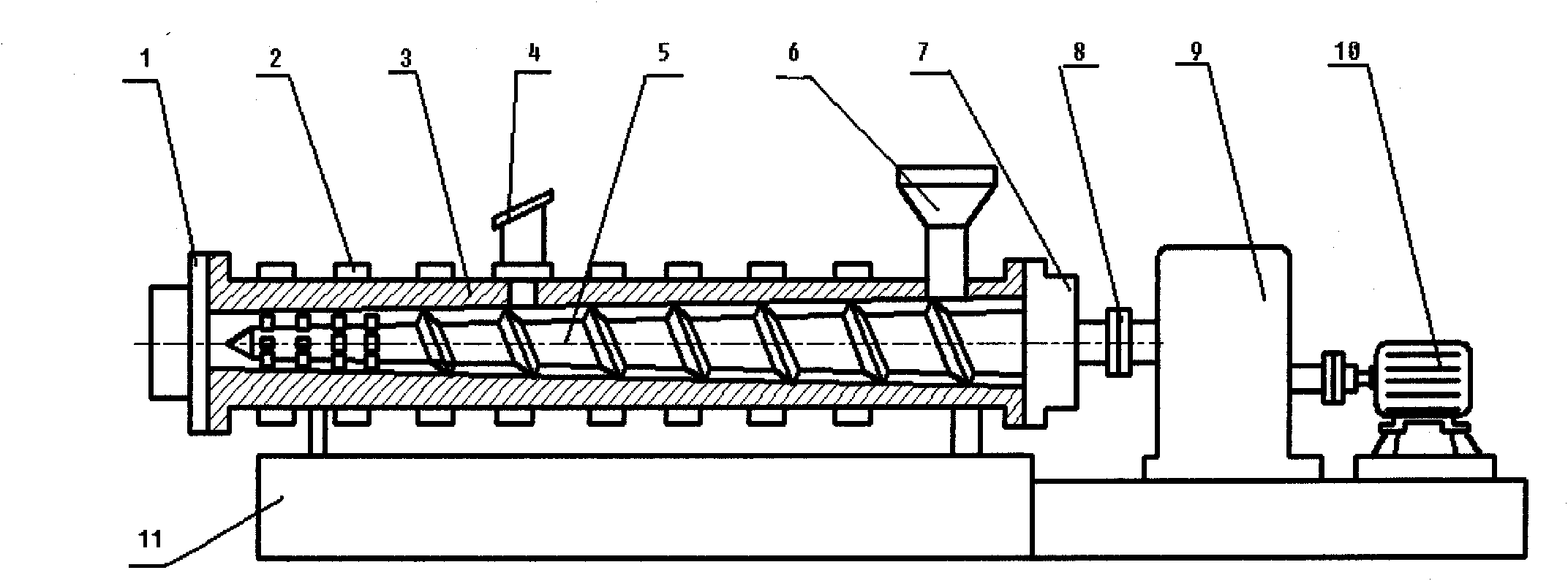
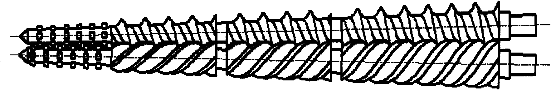
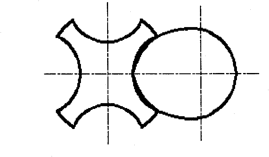
[0021] according to figure 1 Design a differential speed conical twin-screw extruder, the screw meshing like figure 2 . Two conical screws 5 in the extruder adopt image 3 Arrangement form. figure 2 for figure 1 In the two screws, the screws are divided into Yin and Yang rotors, figure 2 The upper middle screw is a male rotor, and the lower screw is a female rotor. Among them, in the threaded meshing area, the number of male rotor threaded edge heads is 1, and the number of female rotor threaded edge heads is 4. The high-speed motor distributes the torque to the male and female rotors through the reduction box 9 and the coupling 8, and the speed ratio is 1 / 4. The two male rotors rotate in the same direction, while the female rotor and the male rotor rotate in different directions. The screw 5 is assembled and placed in the barrel 3 fixed on the mounting seat 7. The barrel 3 is provided with an exhaust port 4, and the temperature is adjusted by...

Example Embodiment

[0023] Implementation case two

[0024] Similar to implementation case 1, a differential conical twin-screw extruder is formed. The difference is that the number of screw heads of the male rotor is 2, and the number of screw heads of the female rotor is 3 (see the screw differential meshing Figure 4 ), after the speed distribution of the reduction box, the ratio of the speed of the female and male rotors is 2 / 3; the screw is in the mixing section near the head 1, using Image 6 with Figure 7 The shown form of intermeshing disc facilitates distributed mixing.


PUM


Abstract

The invention discloses a differential-speed conical twin-screw extruder mainly consisting of a machine head, a heating and cooling device, a machine barrel, an air outlet, two screws, a feeder, a driving device and a motor. The two screws are conical screws, have different numbers of screw flights and are divided into a female rotor and a male rotor, and the ratio of revolutions of the female rotor to the male rotor is in inverse proportion to the ratio of the numbers of the screw flights of the female rotor to the male rotor; the screws are at least provided with a thread meshing region during combination, the number of the screw flights of the female rotor is integral multiple of that of the male rotor in the thread meshing region, and the ratio of the rotation speeds of the female rotor to the male rotor is in inverse proportion to the ratio of the numbers of the screw flights of the female rotor to the male rotor, thus differential-speed rotation can be realized, and the female rotor and the male rotor are not influenced during motion. According to material processing requirements, thread sections with different leads and section molded lines or other forms can be arranged on different sections, such as a feeding section, a fusing section, an exhaust section and a measuring section of each screw, and the screws can be meshed and can not be meshed in different sections during mounting, besides at least one thread meshing region rotated in differential speeds is ensured, thus a function of reinforcing mixing or other functions can be realized. The extruder disclosed by the invention has excellent mixing, plasticizing and conveying capabilities and is suitable for machine-shaping of various granular materials, powder materials, even block materials, such as plastics, rubber, foods, explosives and the like.

Description

technical field [0001] The differential speed conical twin-screw extruder of the present invention is widely used in industries such as petroleum, chemical industry, rubber, plastics, food, pharmacy, explosives and propellant, and the extruder has good mixing, plasticizing, conveying and extruding It is suitable for mixing, granulating, reaction processing and extrusion molding of various granules, powders and even blocks such as plastics, rubber, food and explosives. Background technique [0002] In industries such as petroleum, chemical, rubber, plastic, pharmaceutical, food, explosives and propellants, it is often involved in the mixing, shearing and plasticizing of high-viscosity fluids. Extruders and kneaders are used to achieve these functions. important equipment. [0003] The twin-screw extruder can be significantly better than the single-screw in terms of mixing effect and output. Twin-screw extruders are divided into parallel twin-screw extruders and conical twin...

Claims


Application Information

Patent Timeline
IPC IPC(8): B29C47/40B29C47/60B29C48/585B29C48/40B29C48/42
CPCB29C48/42B29C48/585B29C48/40
Inventor 王克俭
Owner BEIJING UNIV OF CHEM TECH
Why Eureka
Try Eureka