Energy-saving polysilicon reduction furnace and manufacturing method for polysilicon

A manufacturing method and reduction furnace technology, applied in chemical instruments and methods, sustainable manufacturing/processing, silicon compounds, etc., can solve problems such as energy dissipation, achieve the effect of improving conversion rate and reducing heat loss

Inactive Publication Date: 2011-10-05
NINGXIA SUNSHINE SILICON IND CO LTD
View PDF4 Cites 23 Cited by
  • Summary
  • Abstract
  • Description
  • Claims
  • Application Information

AI Technical Summary

Problems solved by technology

This structure obviously caus

Method used


Image

  • Energy-saving polysilicon reduction furnace and manufacturing method for polysilicon
  • Energy-saving polysilicon reduction furnace and manufacturing method for polysilicon
  • Energy-saving polysilicon reduction furnace and manufacturing method for polysilicon

Examples


Embodiment 1

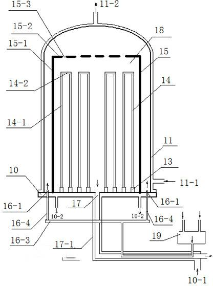
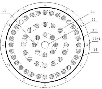
[0042] use as figure 1 and image 3 In the reduction furnace with the structure shown, after installing 28 groups of silicon core rods, the heat shield 15 and the bell-type furnace wall 11 are successively placed on the chassis 10; after the reduction furnace chamber is replaced with nitrogen, the reduction is replaced with hydrogen In the furnace chamber, use 8~12KV voltage to activate the silicon core rod to conduct electric heating, heat the silicon core rod to 1100℃~1200℃, and then feed the raw gas into the gas mixing chamber. Such as figure 1 As shown, the raw gas enters the gas mixing chamber 19, the mixed gas is preheated by the tail gas coming out of the exhaust port 17, and then the mixed gas is drawn out from the pipeline 17-1 through a pipeline and then used an annular coil 16-3 Separate the mixed gas from such as figure 1 Riser 16-4 shown, from as image 3 The 16 evenly distributed raw material gas inlets 16-1 are fed into between the bell-type heat shield and ...

Embodiment 2

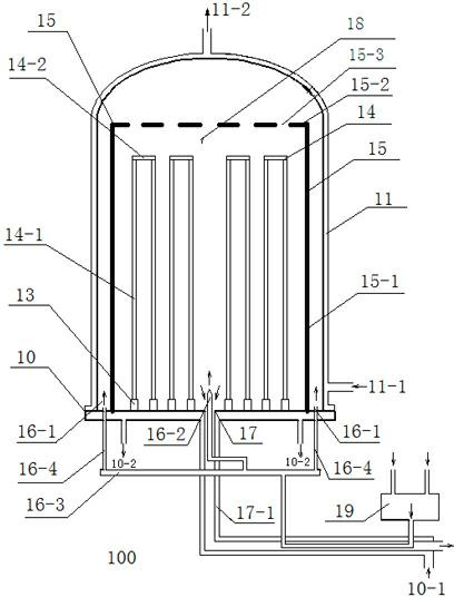
[0044] use as figure 2 and Figure 4 In the reduction furnace shown in the structure, two long silicon core rods 14-1 and one short silicon core rod 14-2 are formed into a group, one end of the long silicon core rod is sharpened as the upper end, and the two ends of the short silicon core rod are cut The hole is matched with it, the tip is inserted into the hole as a group, and a total of 28 groups of silicon core rods 14 are erected on the electrode chuck 13; the heat shield 15 and the bell-type furnace wall 11 are successively placed on the chassis 10; After replacing the chamber of the reduction furnace with nitrogen, replace the chamber of the reduction furnace with hydrogen, preheat the silicon core rod 14 with a graphite heater or a refractory metal heater to become a conductor, and heat the silicon core rod 14 to 1100°C~1200°C ℃; figure 2 As shown, the raw gas enters the gas mixing chamber 19, and the mixed gas is preheated by the exhaust gas coming out from the exh...


PUM


Abstract

The invention relates to an energy-saving polysilicon reduction furnace and a manufacturing method for polysilicon. The polysilicon reduction furnace comprises a bell jar type furnace wall, a base plate arranged on the lower side of the furnace wall, electrodes arranged on the base plate, silicon core rods arranged on the electrodes, and a raw material gas inlet and a tail gas outlet which are formed in the base plate. The polysilicon reduction furnace is characterized in that: the base plate is provided with a bell jar type heat screen which is concentric with the furnace wall and covers the silicon core rods; the heat screen consists of a cylinder part and a top part which is connected with the cylinder part and provided with a through hole; the raw material gas inlet is at least partially formed in the base plate between the cylinder part of the heat screen and the furnace wall; and the tail gas outlet is formed in the center of the base plate. In the polysilicon reduction furnace, the polysilicon is covered by the heat screen, so that the heat loss is reduced to a great extent, raw material gas is preheated, and the conversion rate of trichlorosilane can be improved.

Description

technical field [0001] The invention relates to a polysilicon manufacturing device and a polysilicon manufacturing method. Chemical vapor deposition is performed to deposit polysilicon on the surface of a heated silicon core rod to manufacture polysilicon rods. Background technique [0002] High-purity polysilicon is generally produced by the Siemens method. The raw material gas containing chlorosilane, such as a mixture of trichlorosilane and hydrogen, is brought into contact with a heated silicon core rod, so that the raw material gas is decomposed and / or reduced. Polysilicon is precipitated on the surface. The thermal decomposition of trichlorosilane and the reaction formula with hydrogen are the following formulas (1) and (2): [0003] 4SiHCl 3 → Si + 3SiCl 4 +H 2 ------(1) [0004] SiHCl 3 + H 2 → Si + 3HCl ------(2) [0005] The reduction furnace usually used to generate polysilicon by the modified Siemens method is a bell-shaped furnace wall with cooling w...

Claims


Application Information

Patent Timeline
IPC IPC(8): C01B33/035
CPCY02P20/10
Inventor 张春林浦全福刘军陈艳梅孙银祥陈国奇杨君潘伦桃
Owner NINGXIA SUNSHINE SILICON IND CO LTD
Why Eureka
Try Eureka