Transmission device of washing machine

A transmission device, washing machine technology, applied in washing devices, other washing machines, textiles and papermaking, etc., can solve the problems of lack of integrity, high preparation cost, inconvenient use, etc., and achieve simple and compact, long service life, compact structure. Effect

Inactive Publication Date: 2012-08-08
CHANGZHOU MASTER MACHINERY
View PDF6 Cites 0 Cited by
  • Summary
  • Abstract
  • Description
  • Claims
  • Application Information

AI Technical Summary

Problems solved by technology

This kind of brake mechanism has always had problems such as lack of integrity, complex structure, large volume, inconvenient use, miniaturization of the transmission device, and high manufacturing cost.

Method used


Image

  • Transmission device of washing machine
  • Transmission device of washing machine
  • Transmission device of washing machine

Examples


Embodiment 1

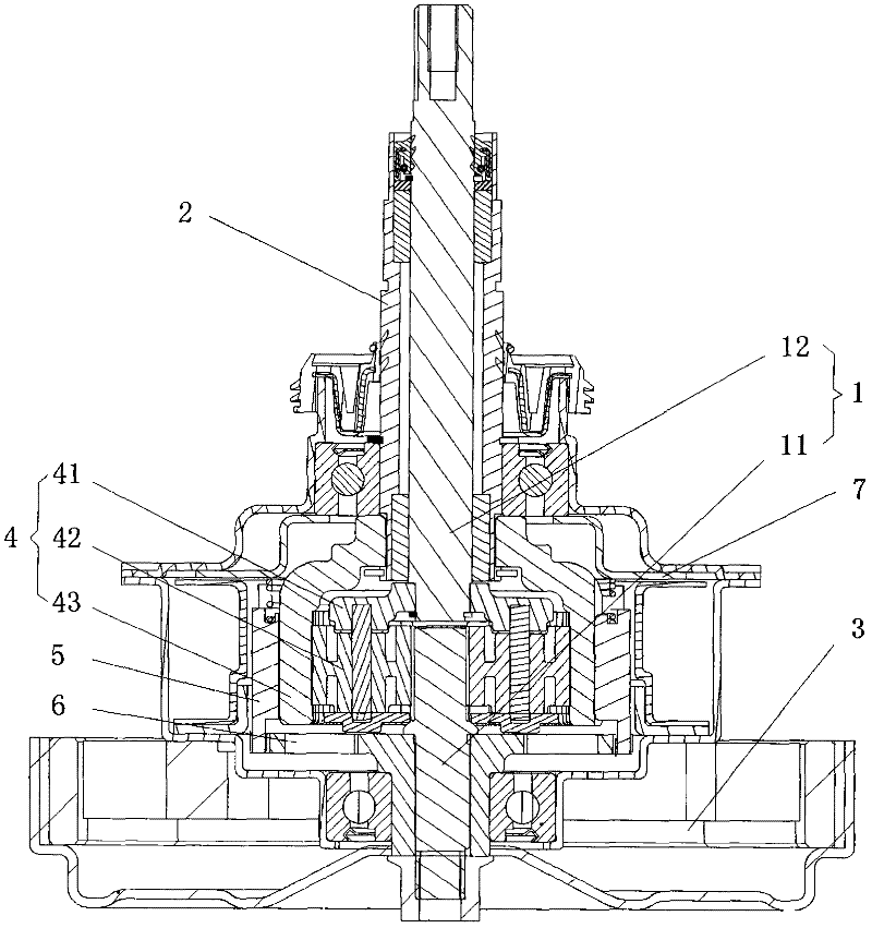
[0058] Embodiment 1, as figure 2 , Figure 4 , Figure 5 , Figure 8 with Figure 9 As shown, a washing machine transmission device includes a drive shaft 21, a drive sleeve 22, a clutch 23, a stator assembly 24, a rotor assembly 25, and a brake mechanism 30, wherein the drive shaft 21 is rotatably arranged in the drive sleeve 22, and the clutch 23 controls The rotation of the drive shaft 21 and the drive sleeve 22, wherein: the stator assembly 24 is located in the rotor assembly 25; the clutch 23 includes a clutch ring gear 2310 and an electromagnetic coil 232 located outside the clutch ring gear 2310, and the clutch ring gear 2310 includes a The magnetically conductive part 2312 and the non-magnetically permeable part 2311 located inside, the magnetically permeable part 2312 and the non-magnetically permeable part 2311 are fixedly connected as one, and the non-magnetically permeable part 2311 is engaged with the external teeth of the drive bushing 22 to slide up and down...

Embodiment 2

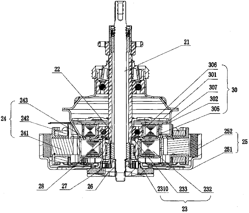
[0059] Embodiment 2, as image 3 , Figure 4 , Figure 5 , Figure 8 with Figure 9As shown, a washing machine transmission device includes a drive shaft 21, a drive sleeve 22, a clutch 23, a stator assembly 24, a rotor assembly 25, and a brake mechanism 30, wherein the drive shaft 21 is rotatably arranged in the drive sleeve 22, and the clutch 23 controls The rotation of the drive shaft 21 and the drive shaft sleeve 22, wherein: the drive shaft 21 includes a power shaft 211 and an output shaft 212 coaxially arranged in the up and down direction, the power shaft 211 is used to receive the rotational force of the rotor assembly 25, and the output shaft 212 It is used to connect the pulsator and output the rotational force accordingly; the drive bushing 22 includes an input bushing 221 and an output bushing 222 coaxially arranged in the up and down direction; the stator assembly 24 is located in the rotor assembly 25; the clutch 23 includes a clutch The ring gear 2310 and th...

Embodiment 3

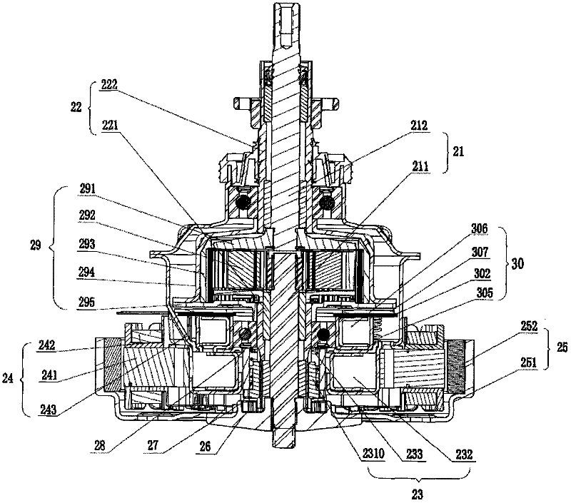
[0060] Embodiment 3, as Image 6 with Figure 7 As shown, a transmission device for a washing machine, wherein the coupling 26 is made of non-magnetic material; the clutch ring gear 2310 includes an outer magnetic member 2312 and an inner non-magnetic member 2311 , the magnetically conductive part 2312 and the non-magnetically conductive part 2311 are fixedly connected as one, the non-magnetically conductive part 2311 and the external teeth of the input shaft sleeve 221 can slide up and down, and the upper and lower ends of the magnetically conductive part 2312 are evenly distributed with slotted teeth; the shaft coupling The gear 26 is provided with an engaging part 27 that can be engaged with the groove teeth distributed at the lower end of the magnetic conducting part 2312, and the engaging part 27 and the shaft coupling 26 are of an integrated structure; The meshing part 28 of groove tooth meshing, all the other are with embodiment 2.


PUM


Abstract

The invention relates to a part of a washing machine, in particular to a transmission device of the washing machine. The transmission device comprises a drive shaft, a drive shaft sleeve, a clutch, a stator component, a rotor component and a brake mechanism, wherein the drive shaft is rotatably arranged in the drive shaft sleeve; the clutch controls the rotation of the drive shaft and the drive shaft sleeve; the stator component is positioned in the rotor component; the rotor component is fixedly connected with one end of the drive shaft through a coupler; the clutch comprises a sliding pieceand an electromagnetic coil positioned outside the sliding piece; the sliding piece can be meshed with the external teeth of the drive shaft sleeve in a vertical sliding mode; a meshing part which can be meshed with the sliding piece is arranged at the joint of the rotor component and the drive shaft; the stator component is provided with a meshing part which can be meshed with the sliding piece;the brake mechanism comprises a brake plate, a brake disc and a brake disc retainer; and the brake plate is fixedly connected with the drive shaft sleeve. The transmission device has a simple and compact structure, small volume and low manufacturing cost, and is flexibly controlled.

Description

technical field [0001] The invention relates to a washing machine component, in particular to a washing machine driving device. Background technique [0002] The washing machine is a machine that removes stains attached to the laundry through chemical decomposition and mechanical impact. The main work of the washing machine is driven by the main shaft to rotate the pulsator, stirring the water flow and the rotation of the clothes to achieve the purpose of washing the clothes. Since the clothes cannot be strongly rubbed, the speed of the pulsator is generally limited to a certain extent and cannot be too fast. Due to the limitation of space, most of the existing washing machines directly drive the main shaft to drive the pulsator through the drive motor, and the purpose of reducing the internal space of the washing machine is achieved by removing the pulley drive and the mechanical transmission mechanism that drive the washing machine. If the drive motor is used to directly ...

Claims


Application Information

Patent Timeline
Patent Type & Authority Patents(China)
IPC IPC(8): D06F37/30
Inventor 宋庆章胡义明朱剑力陈昌
Owner CHANGZHOU MASTER MACHINERY
Why Eureka
Try Eureka