Al technical title is built by PatSnap Al team. It summarizes the technical point description of the patent document.
A technology of couplings and balls, applied in couplings, elastic couplings, mechanical equipment, etc., can solve the problems of rubber elastic fatigue damage, low efficiency, and reduced torsional vibration strength of elastomers, so as to improve the bearing capacity. and stiffness, fast coupling and disassembly, reducing the effect of unbalanced moments
Inactive Publication Date: 2011-10-05
CHONGQING AEROSPACE POLYTECHNIC COLLEGE
View PDF7 Cites 1 Cited by
Summary
Abstract
Description
Claims
Application Information
AI Technical Summary
This helps you quickly interpret patents by identifying the three key elements:
Problems solved by technology
Method used
Benefits of technology
Problems solved by technology
[0002] Under normal working conditions, after a long period of use, ordinary rubber couplings are prone to elastic fatigue damage of the rubber, the torsional vibration strength of the elastic body is reduced, and the torsional torque is reduced, which leads to the failure of the elastic body and cannot compensate for the shaft transmission. The misalignment error generated during the installation and operation of the mechanism; the drum-shaped gear coupling has the disadvantages of high process requirements, high vibration noise, poor economy and pollution of the surrounding environment; The load needs to be used in pairs during installation, the axial distance is long, the volume is huge, and the error of the transmission is large at the same time
[0003] Most of the coupling halves are connected by bolts and nuts. Special tools are required for installation and disassembly, which is time-consuming, labor-intensive, inefficient and economical.
Method used
Image
Click on the blue label to locate the original text in one second.
Reading with bidirectional positioning of images and text.
Examples
Embodiment Construction
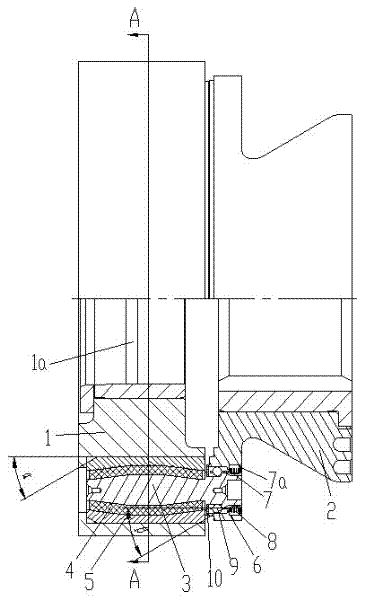
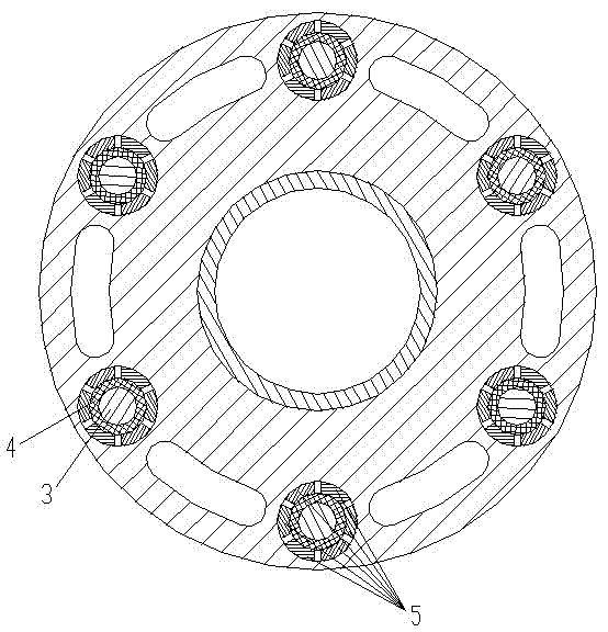
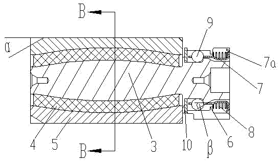
[0022] attached figure 1 A half-sectional view of the overall structure of the quick coupling ball coupling, attached figure 2 for figure 1 Sectional view along A-A direction, attached image 3 It is a schematic diagram of the assembly structure between the coupling body, the cage and the steel ball, and the attached Figure 4 for image 3 Sectional view along BB direction.
[0023] As shown in the figure, the quick coupling ball pair coupling of the present invention includes an input shaft flange 1 for fixed connection with the input shaft and an output shaft flange 2 for fixed connection with the output shaft, the input shaft Blind holes are evenly distributed along the axial direction of the coupling on the circumference of the flange 1, and through holes corresponding to the blind holes are uniformly distributed along the axial direction of the output shaft flange 2 along the axial direction of the coupling, including A connecting body that connects the input shaft ...
PUM
Abstract
The invention discloses a quick connecting ball pair type coupler which comprises an input shaft flange plate, an output shaft flange plate and a connector, wherein the connector comprises a core shaft, a rubber elastomer is arranged at one end of the core shaft in a wrapped manner, metal blocks are uniformly arranged on an outer circumferential surface of the rubber elastomer, the core shaft, the rubber elastomer and the metal blocks are adhered to form an integrated structure, a boss is arranged on the outer circumferential surface at the other end of the core shaft, a jacket is provided with a retainer which is provided with a barb, a spring is fixedly arranged on the end of the retainer, which is close to the barb, a group of circular holes are uniformly arranged in the end of the retainer, which is away from the barb, along a circumferential direction, steel balls are arranged in the circular holes, the end of the connector, which is provided with the rubber elastomer, is arranged in a blind hole of the input shaft flange plate, and the other end of the connector is arranged in a through hole of the output shaft flange plate. When the quick connecting ball pair type coupler disclosed by the invention is adopted, two shafts can be coupled and disassembled quickly and conveniently, and rotation errors are reduced to a certain extent; and moreover, the quick connecting ball pair type coupler has the advantages of low energy consumption, safety, reliability, compact structure and high power.
Description
technical field [0001] The invention relates to a transmission device, in particular to a coupling. Background technique [0002] Under normal working conditions, after a long period of use, ordinary rubber couplings are prone to elastic fatigue damage of the rubber, the torsional vibration strength of the elastic body is reduced, and the torsional torque is reduced, which leads to the failure of the elastic body and cannot compensate for the shaft transmission. The misalignment error generated during the installation and operation of the mechanism; the drum-shaped gear coupling has the disadvantages of high process requirements, high vibration noise, poor economy and pollution of the surrounding environment; The load needs to be used in pairs during installation, the axial distance is long, the volume is large, and the transmission error is large. [0003] Most of the coupling halves are connected by bolts and nuts. Special tools are required for installation and disassemb...
Claims
Application Information
Patent Timeline
Application Date:The date an application was filed.
Publication Date:The date a patent or application was officially published.
First Publication Date:The earliest publication date of a patent with the same application number.
Issue Date:Publication date of the patent grant document.
PCT Entry Date:The Entry date of PCT National Phase.
Estimated Expiry Date:The statutory expiry date of a patent right according to the Patent Law, and it is the longest term of protection that the patent right can achieve without the termination of the patent right due to other reasons(Term extension factor has been taken into account ).
Invalid Date:Actual expiry date is based on effective date or publication date of legal transaction data of invalid patent.