
Oil supply construction for power transmission mechanism

A power transmission mechanism and oil supply technology, which is applied to gear lubrication/cooling, control devices, vehicle components, etc., can solve difficult oil supply problems and achieve the effect of improving strength

Active Publication Date: 2014-06-18
HONDA MOTOR CO LTD
View PDF8 Cites 0 Cited by
  • Summary
  • Abstract
  • Description
  • Claims
  • Application Information

AI Technical Summary

Problems solved by technology

[0004] However, as in the prior art described above, the structure in which oil is blown up with the rotation of gears and the like is applied to a first rotating body such as a starting clutch on the crankshaft and a centrifugal filter, and a second rotating body such as a transmission clutch on the main shaft. In the case of the engine, since the two rotating bodies are offset from each other in the axial direction, it is difficult to supply the raised oil to the rotating body on the other side.

Method used


Image

  • Oil supply construction for power transmission mechanism
  • Oil supply construction for power transmission mechanism
  • Oil supply construction for power transmission mechanism

Examples


Embodiment Construction

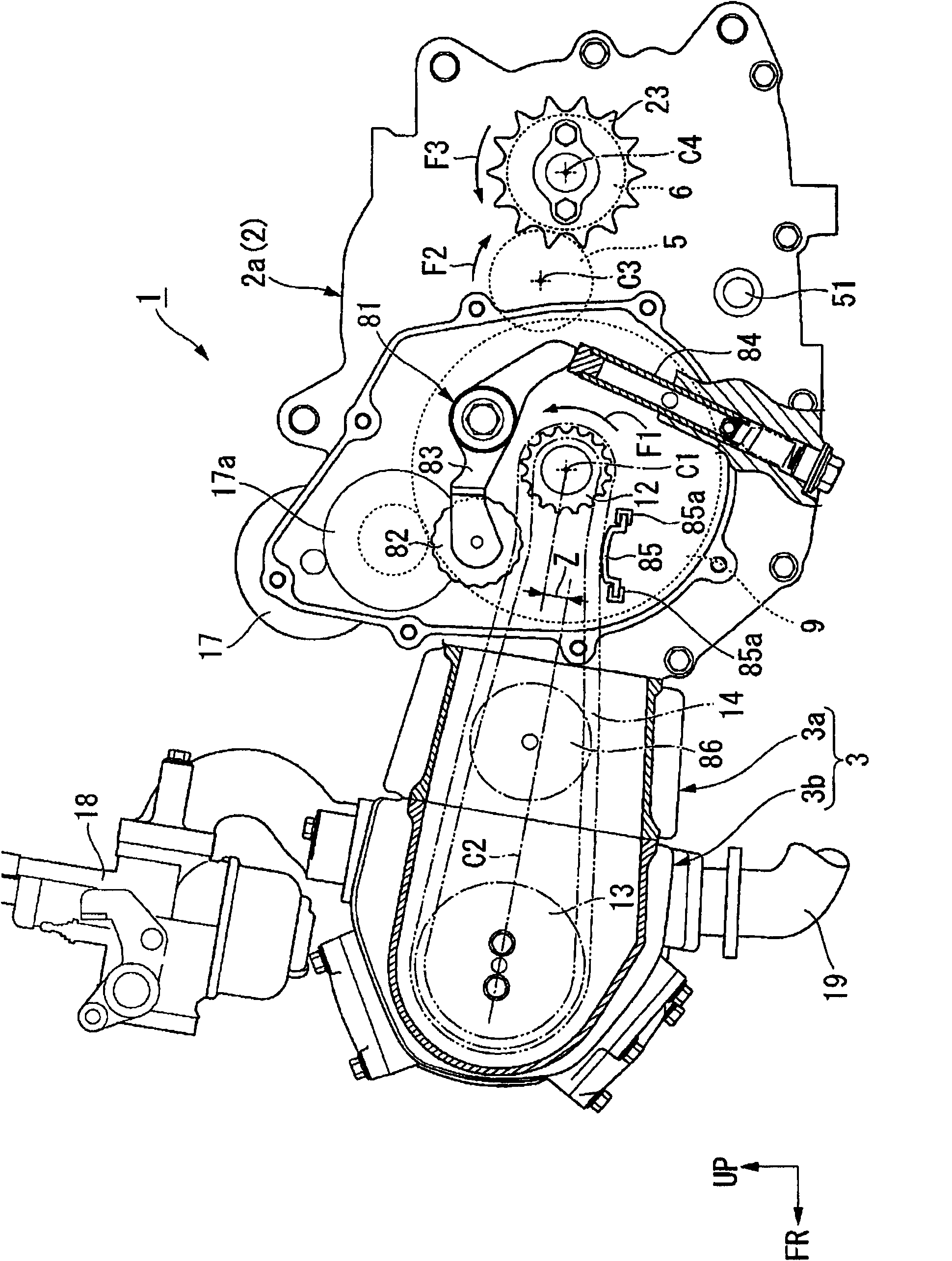
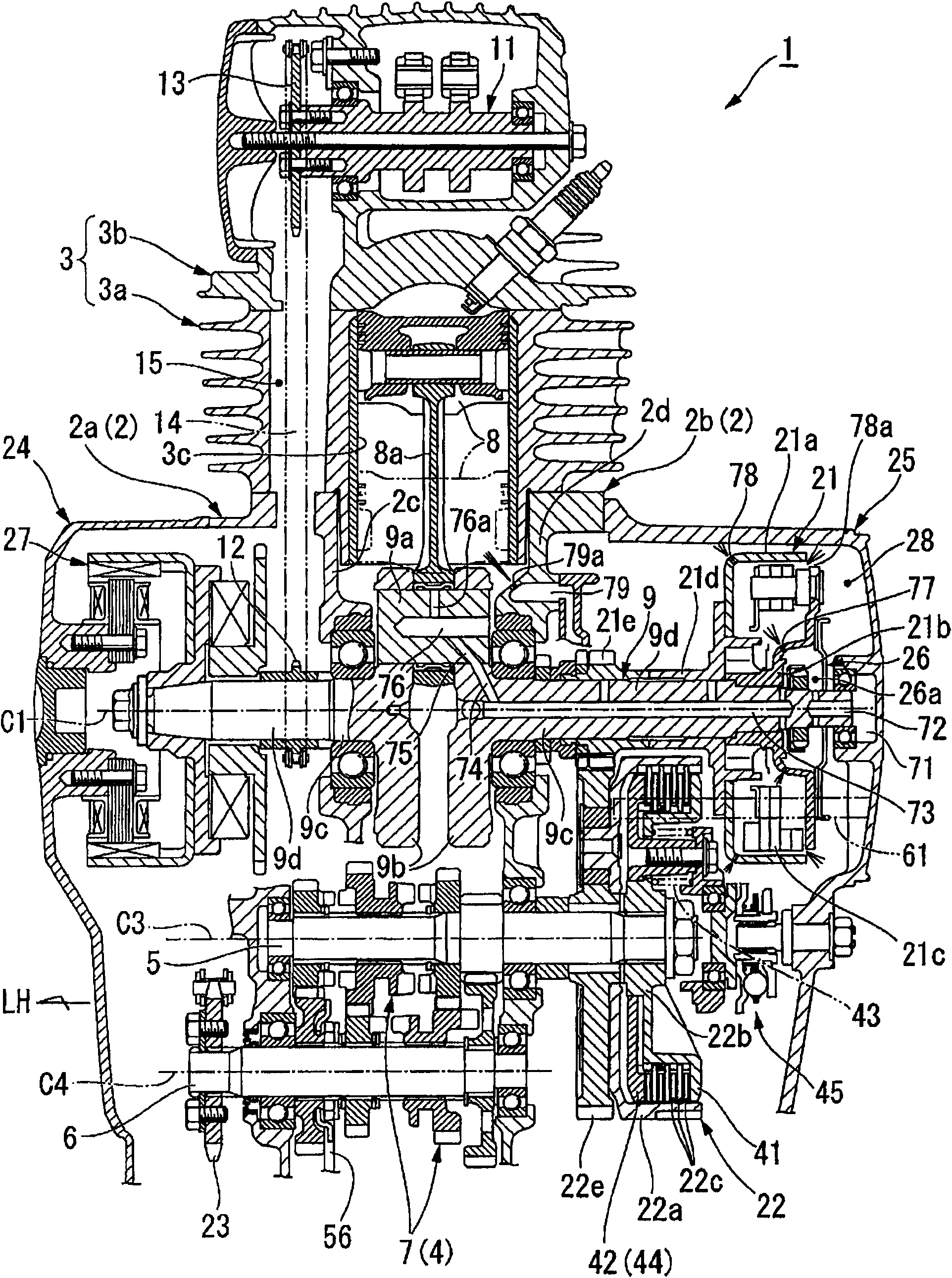
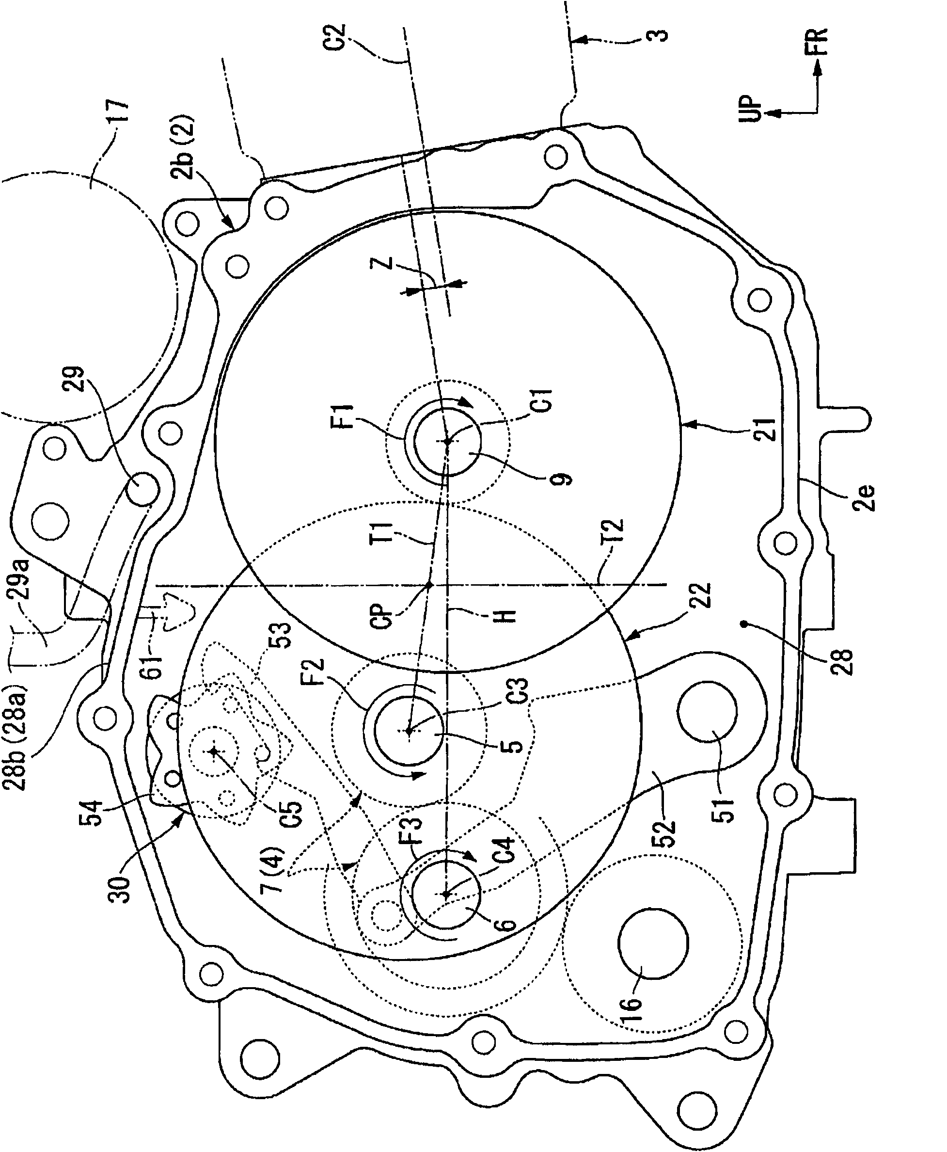
[0051]Hereinafter, embodiments of the present invention will be described with reference to the drawings. In addition, in the following description, the directions such as front, rear, left, and right will be described with the arrow FR shown at an appropriate position in the figure as the front, the arrow LH as the left side, and the arrow UP as the upward direction unless otherwise specified.

[0052] Figure 1~3 The shown engine (internal combustion engine) 1 is mounted as a prime mover on a straddle-type vehicle such as a two-wheeled motorcycle, and is an air-cooled single-cylinder engine in which the rotation center axis (crank axis) C1 of the crankshaft 9 is along the left-right direction, and has A basic structure in which the cylinder 3 projects substantially horizontally (specifically, slightly forward and upward) forward from the front end of the crankcase 2 . In addition, reference numeral C2 in the figure denotes an axis (cylinder axis) along the protruding direct...


PUM


Abstract

The invention provides an oil supply construction for a power transmission mechanism, in an oil supply construction for a power transmission mechanism provided with a startup clutch and a speed change clutch in a split way, spray oil in a crankshaft case is effectively utilized to well perform oil supply to two clutches. The oil supply construction in the invention is provided with: a first oil supply hole (77) opened towards the internal of a centrifugal clutch (21) and used for supplying oil from a second oil path (72) formed at a shaft center of a crankshaft (9) to the centrifugal clutch (21); a second oil supply hole (78) and a gap (78a) disposed at a clutch external part (21a) of the centrifugal clutch (21) and directed towards the side opening of a multi-plate clutch (22); and a rib (61) at an upper part of the multi-plate clutch (22) observed axially and extending downwards from the upper wall portion of a clutch chamber (28).

Description

technical field [0001] The present invention relates to an oil supply structure for a power transmission mechanism used in vehicles such as motorcycles. Background technique [0002] Conventionally, among the above-mentioned oil supply structures, a structure is known in which a rib for capturing spray oil lifted up with the rotation of the gear is provided on the upper wall of the crankcase at a position corresponding to the roller bearing. Oil drips from the ribs to supply oil to the roller bearing (for example, refer to Patent Document 1). [0003] Patent Document 1: Japanese Patent Laid-Open No. 2006-183594 [0004] However, as in the prior art described above, the structure in which oil is blown up with the rotation of gears and the like is applied to a first rotating body such as a starting clutch on the crankshaft and a centrifugal filter, and a second rotating body such as a transmission clutch on the main shaft. In the case of a conventional engine, since the two ...

Claims


Application Information

Patent Timeline
Patent Type & Authority Patents(China)
IPC IPC(8): F16H57/04B60K17/02
Inventor 内田博之山本敏弘尾高春彦
Owner HONDA MOTOR CO LTD
Learn More