Solar cell

A solar cell and battery technology, applied in the field of solar cells, can solve the problems of reduced power generation efficiency, shadow loss, carrier recombination loss, etc., and achieve the effect of high power generation efficiency

Inactive Publication Date: 2011-10-05
NAPRA
View PDF5 Cites 1 Cited by
  • Summary
  • Abstract
  • Description
  • Claims
  • Application Information

AI Technical Summary

Problems solved by technology

[0005] However, in the above-mentioned structure, there is a problem that the incident light is blocked by the silver electrodes, busbar electrodes, and finger electrodes on the first main surface, and loss due to shadows occurs, and current-carrying occurs at the lower part of the silver electrodes. recombination loss
[0007] However, even in the case where the above-mentioned penetrating electrode structure is adopted, the incident light is blocked by the silver electrode, and loss due to shading still occurs.
Therefore, the result is of course a reduction in power generation efficiency
[0008] Furthermore, since it is necessary to form a plurality of silver electrodes in stripes with intervals on the first main surface, there is a limit to the area expansion of one solar cell.

Method used


Image

  • Solar cell
  • Solar cell
  • Solar cell

Examples


Embodiment Construction

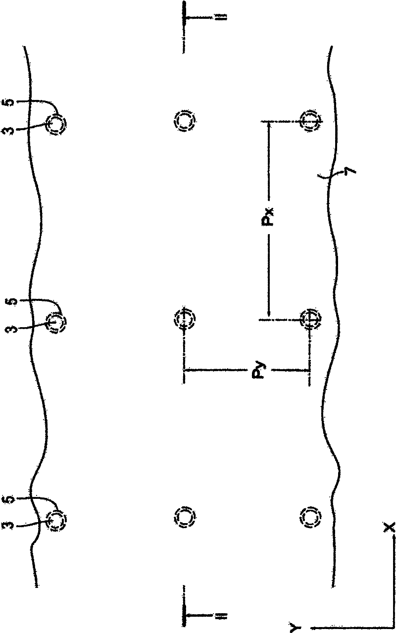
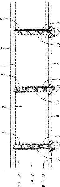
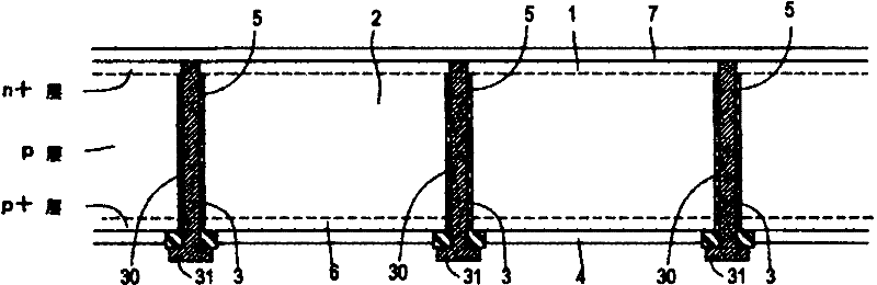
[0026] figure 1 and figure 2 It is a diagram showing a representative example of a crystalline silicon solar cell, and includes a first conductivity type semiconductor layer 1 , a second conductivity type semiconductor layer 2 , a first electrode 3 , and a second electrode 4 .

[0027] The surface of the first conductivity type semiconductor layer 1 serves as a light receiving surface, and the second conductivity type semiconductor layer 2 is provided on the back side of the first conductivity type semiconductor layer 1 to form a pn junction with the first conductivity type semiconductor layer 1 . More specifically, the second conductivity type semiconductor layer 2 is formed of a p-type silicon substrate, and the n+ layer first conductivity type semiconductor layer 1 is formed on the light receiving surface side of the second conductivity type semiconductor layer 2 . Therefore, the second conductivity type semiconductor layer 2 formed of the p-type silicon substrate forms a...


PUM


Abstract

The invention provides a solar cell having high light-receiving efficiency and power generation efficiency per unit area. A solar cell includes a first conductivity-type semiconductor layer (1), a second conductivity-type semiconductor layer (2), a first electrode, and a second electrode. The first conductivity-type semiconductor layer (1) has a front side intended to serve as a light-receiving surface. The second conductivity-type semiconductor layer (2) is disposed on a back side of the first conductivity-type semiconductor layer, forming a p-n junction together with the first conductivity-type semiconductor layer. The first electrode (3) passes through the second conductivity-type semiconductor layer (2) toward the first conductivity-type semiconductor layer (1) with a tip extending into and ending within the first conductivity-type semiconductor layer. The second electrode (4)is disposed at a back side of the solar cell.

Description

technical field [0001] The present invention relates to solar cells. Background technique [0002] In recent years, especially from the viewpoint of global environmental problems, expectations for solar cells as an energy source in the next century have been rapidly increasing. As solar cells, various cells such as silicon-based, compound-based, organic-based, and dye-sensitized solar cells are known. [0003] Among them, the most widely known silicon-based solar cells are, for example, disclosed in JP-A-2009-123761 and JP-A-2008-270743, by forming an n+ layer on the light-receiving surface of a p-type silicon substrate as a semiconductor substrate. , thereby forming a pn junction from the p-type silicon substrate and the n+ layer. [0004] An antireflection film and a silver electrode are respectively formed on the first main surface serving as the light receiving surface of the p-type silicon substrate. The silver electrode is composed of a bus bar electrode for connect...

Claims


Application Information

Patent Timeline
Patent Type & Authority Applications(China)
IPC IPC(8): H01L31/0224H01L31/04H01L31/068
CPCY02E10/50Y02E10/542H01L31/02245Y02E10/546Y02E10/547H01L31/0224H01L31/04H01L31/06
Inventor 关根重信关根由莉奈桑名良治
Owner NAPRA
Why Eureka
Try Eureka