Capacitance compensation fling-cut switch
A switching switch and capacitance compensation technology, which is applied in reactive power compensation, reactive power adjustment/elimination/compensation, cooling/ventilation/heating transformation, etc., can solve the problems of easy short circuit, trouble, high temperature, etc. between wires and secondary lines
- Summary
- Abstract
- Description
- Claims
- Application Information
AI Technical Summary
Problems solved by technology
Method used
Image
Examples
Embodiment 1)
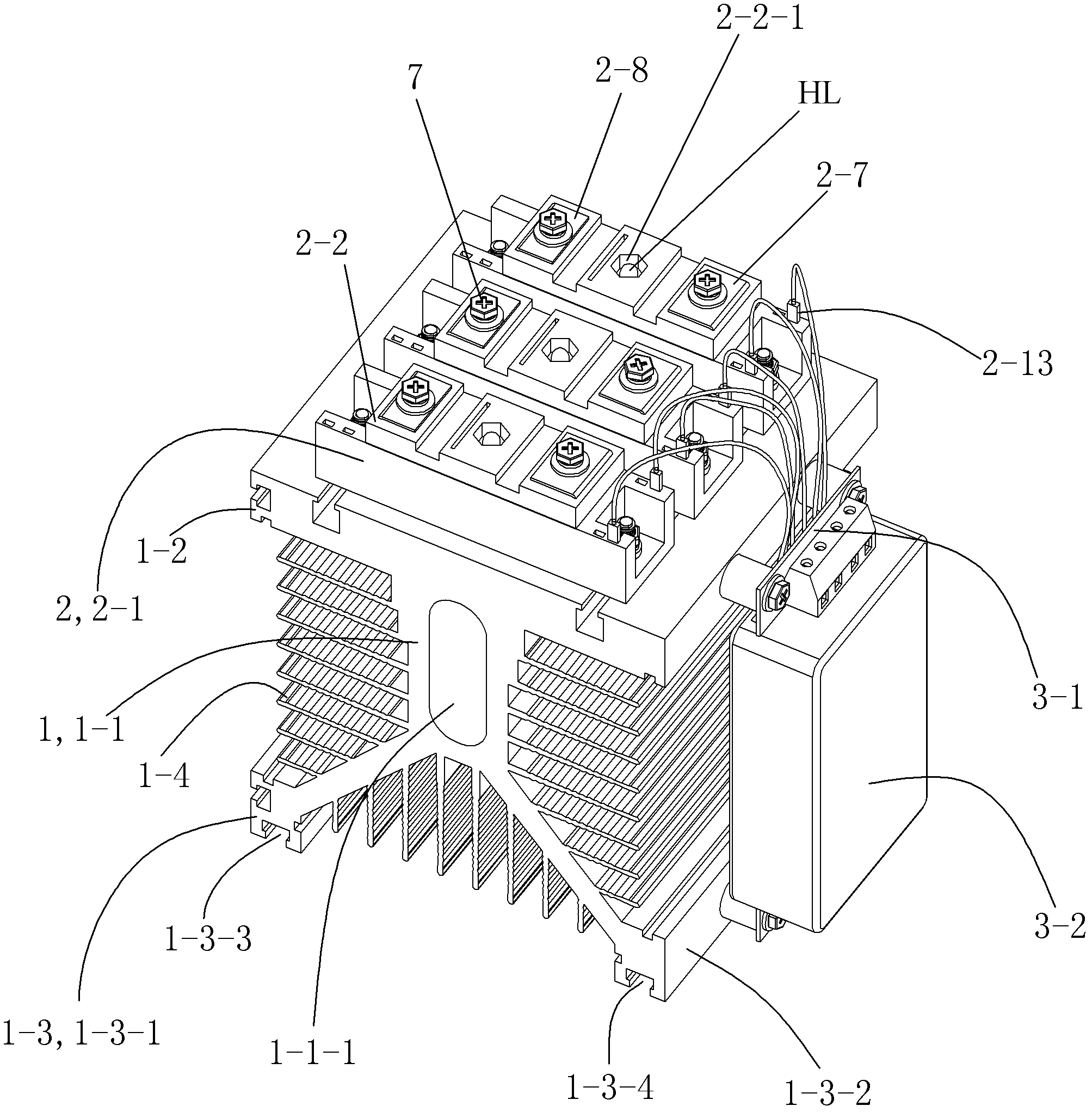
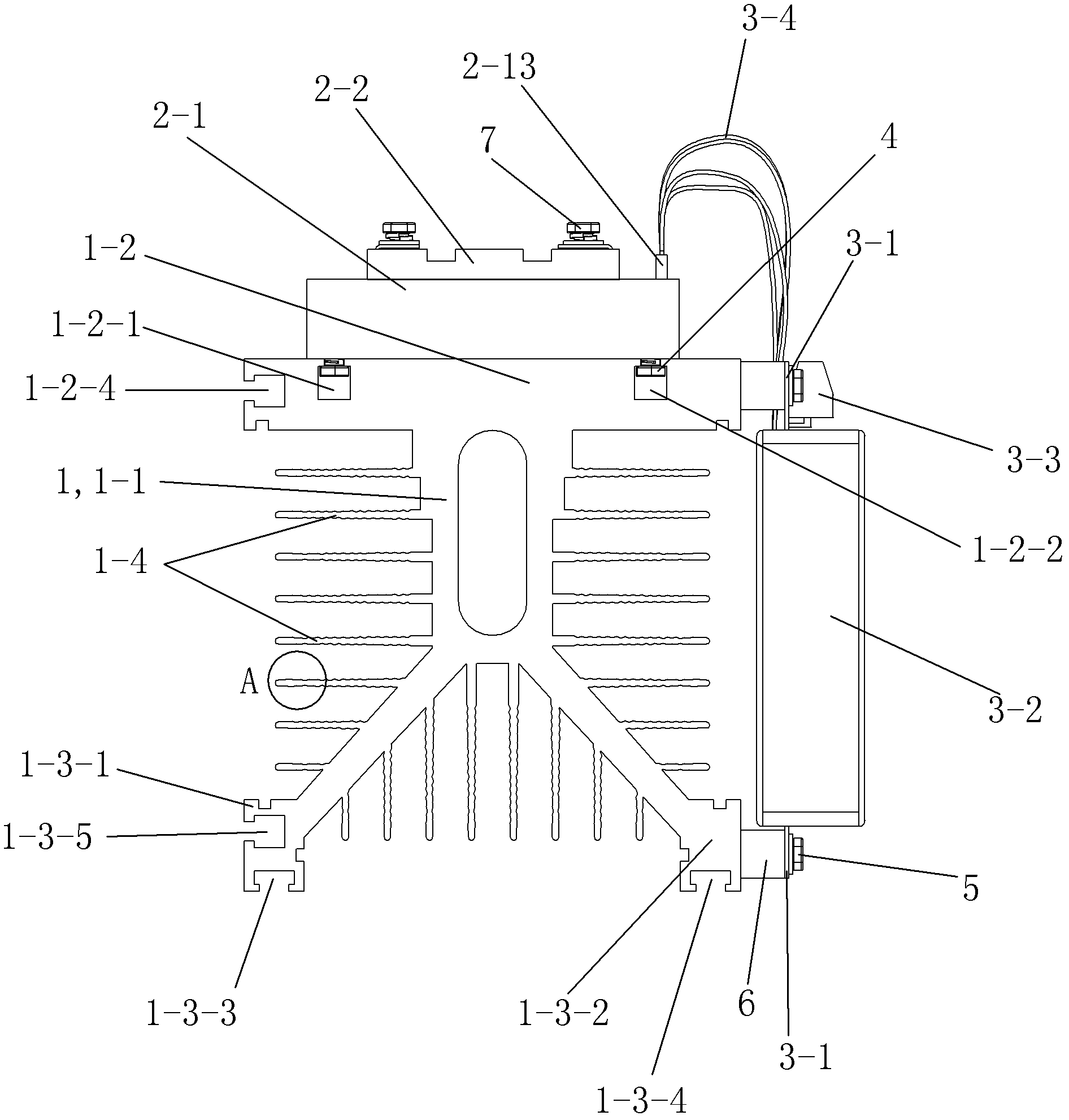
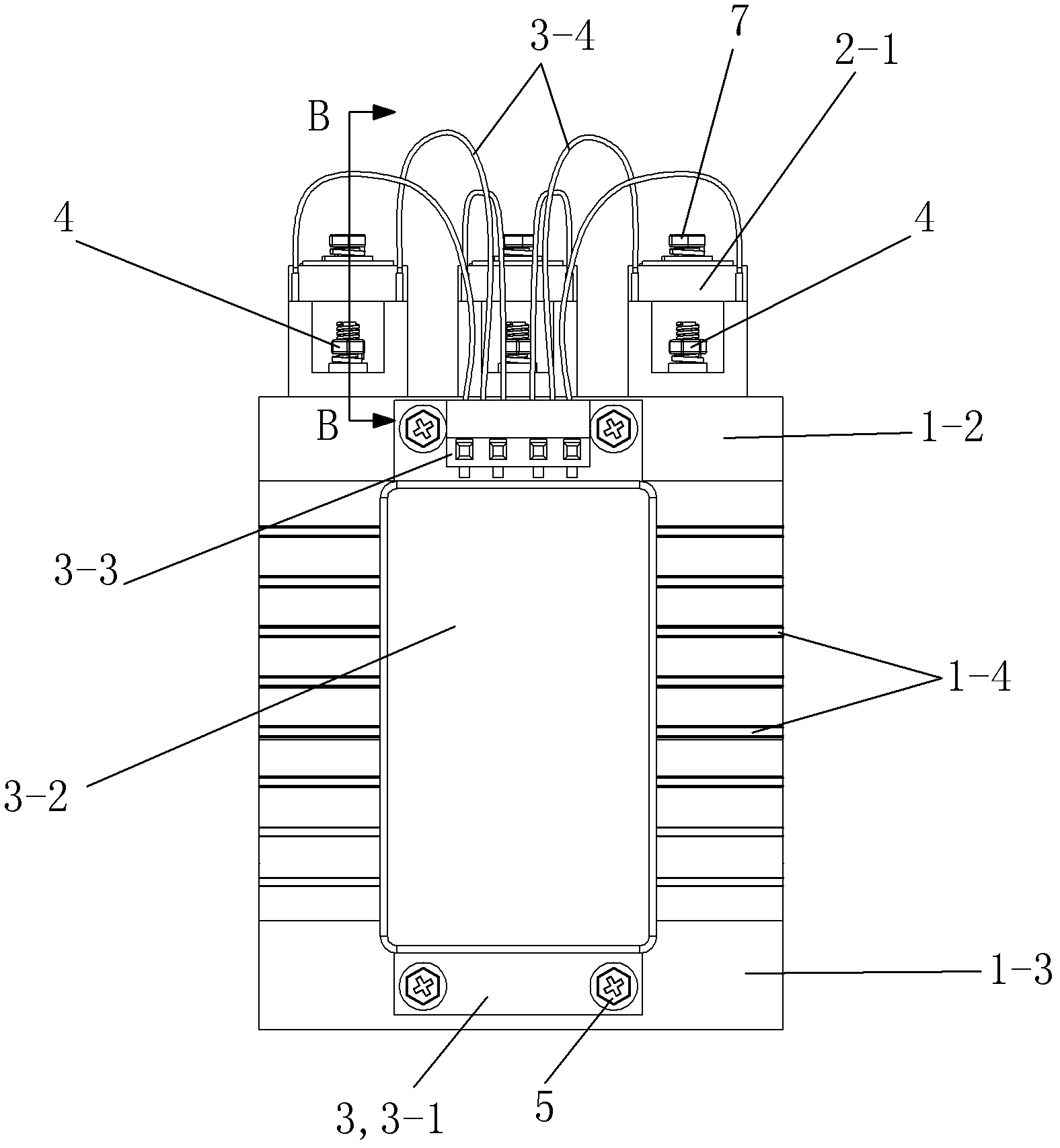
[0044] See figure 1 and figure 2 , the capacitance compensation switching switch of this embodiment (hereinafter referred to as the switching switch) includes a heat dissipation base 1 , a thyristor module 2 and a DC power supply device 3 .
[0045] See Figure 6 , the heat dissipation base 1 is made of an aluminum alloy profile after cutting and drilling. The aluminum alloy profile is obtained by extruding the aluminum alloy bar with the grade of 6063 through a mold of a corresponding shape at a certain temperature. The heat dissipation base 1 includes a heat dissipation support part 1-1, a mounting plate part 1-2, a mounting foot part 1-3 and a heat dissipation fin 1-4. The cross-section of the heat dissipation support part 1-1 is basically rectangular, with a waist-circular heat dissipation hole 1-1-1 in the middle; the installation platen part 1-2 is located above the heat dissipation support part 1-1 and arranged horizontally; the installation The upper side of the p...
Embodiment 2)
[0061] See Figure 11, the rest of this embodiment is the same as that of Embodiment 1, the difference is that: the right side of the mounting plate portion 1-2 of the heat dissipation base 1 is provided with an upper right T-shaped slot 1-2 that opens to the right and is arranged along the front and rear direction -5, and the two platen mounting screw holes 1-2-3 are also removed accordingly. The bottom of the right mounting foot 1-3-2 is also provided with the lower right T-slot 1-3-6 that is positioned at the opening above the lower right T-slot 1-3-4 to the right along the front-to-back direction, and the two installation Screw holes 1-3-7 are also correspondingly removed. The circuit board 3-1 is fixedly connected to the heat dissipation base 1 through the fasteners 4 arranged in the upper right T-shaped slot 1-2-5 and the lower right T-shaped slot 1-3-6.
Embodiment 3)
[0063] The rest of this embodiment is the same as Embodiment 1, the difference is that: the power input junction block 3-3 of the DC power supply device 3 is a two-position power input junction block, and the DC power output leads 3-4 are corresponding 3 groups of 6 root. This switching switch can be used as a three-phase co-compensation capacitor compensation switching switch. When in use, connect one phase of the three-phase AC power supply to the copper first connecting piece 2-7 of each thyristor module 2, so that the copper second connecting piece 2-8 is connected to the corresponding capacitor in an angle connection (△) The corresponding one of the joints of the group is connected.
PUM
 Abstract
Description
Claims
Application Information
 - R&D
- Intellectual Property
- Life Sciences
- Materials
- Tech Scout
- Unparalleled Data Quality
- Higher Quality Content
- 60% Fewer Hallucinations
Browse by: Latest US Patents, China's latest patents, Technical Efficacy Thesaurus, Application Domain, Technology Topic, Popular Technical Reports.
© 2025 PatSnap. All rights reserved.Legal|Privacy policy|Modern Slavery Act Transparency Statement|Sitemap|About US| Contact US: help@patsnap.com


