
Energy-saving device for high-pressure discharge lamp

A technology for high-pressure discharge lamps and energy-saving devices, which is applied to lighting devices, electric light sources, and electrical components, and can solve the problems of increasing the burden on power adjustment components, suddenly extinguishing, and flickering, so as to prevent poor lighting, reduce burdens, and improve life. Effect

Inactive Publication Date: 2013-11-27
KAWAMURA ELECTRIC INC
View PDF5 Cites 0 Cited by
  • Summary
  • Abstract
  • Description
  • Claims
  • Application Information

AI Technical Summary

Problems solved by technology

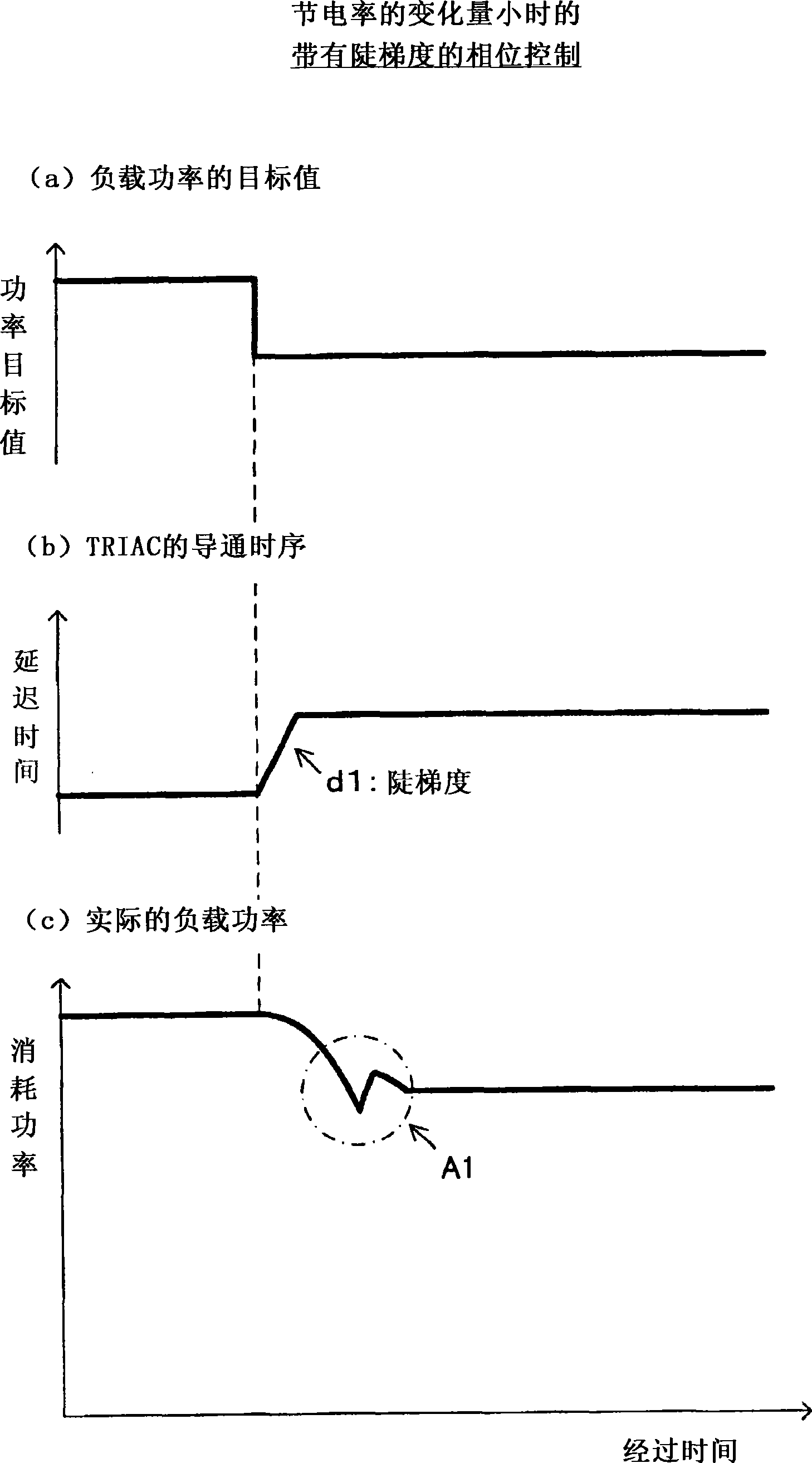
[0004] However, in existing power saving devices, such as Image 6 When the power saving rate is changed as shown in (a) and the power target value is changed, as shown in (b), the timing of turning on the TRIAC (the delay time from the voltage zero crossing, refer to Figure 5 ) instantaneous change
Therefore, if the power saving rate is set high and the turn-on timing of the TRIAC is delayed with a large phase, there will be the following problems: the state of the vapor in the discharge tube will change drastically, and the arc discharge will become unstable, as shown in (c) As shown, the actual load power (power consumption) drops sharply, and the high-pressure discharge lamp flickers or goes out suddenly
However, if Figure 7 As shown, immediately after the power is turned on, a relatively large initial current of about 3 to 5 times the steady current flows for a long time, which increases the burden on the power adjustment element, and the life and reliability of the power saving device may not be stable. question

Method used


Image

  • Energy-saving device for high-pressure discharge lamp
  • Energy-saving device for high-pressure discharge lamp
  • Energy-saving device for high-pressure discharge lamp

Examples


Embodiment Construction

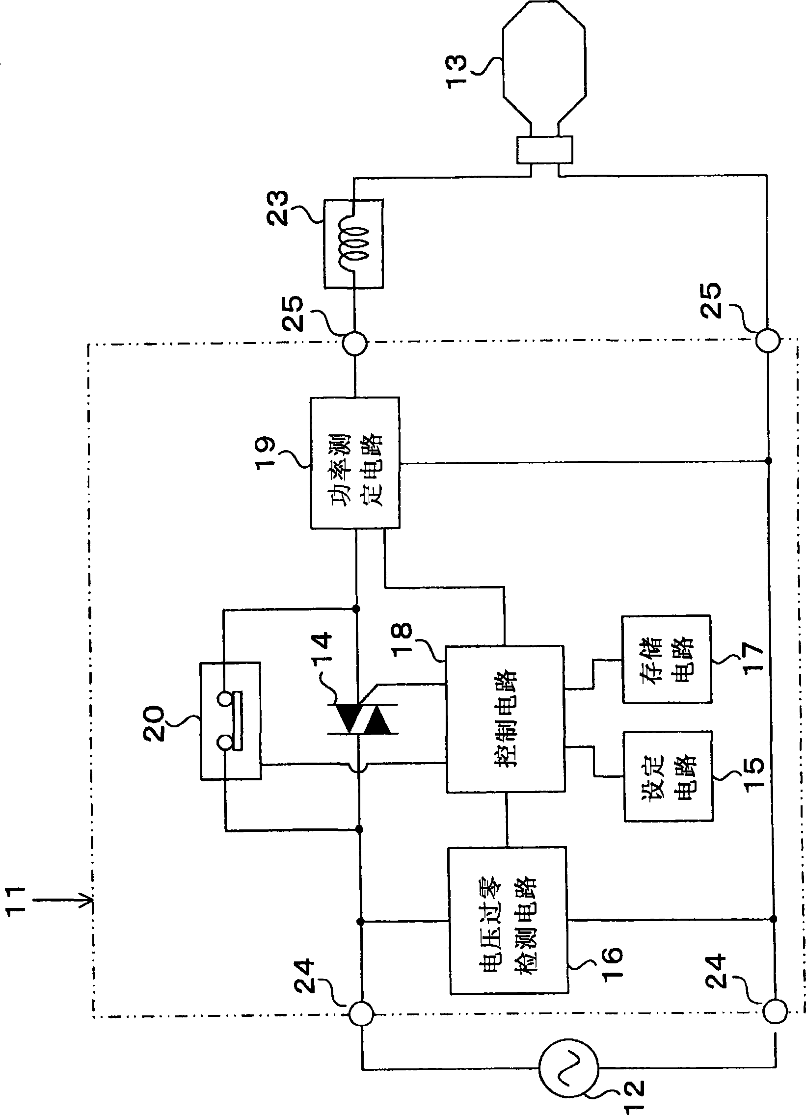
[0020] Embodiments of the present invention will be described below with reference to the drawings. Such as figure 1 As shown, the power saving device 11 of this embodiment includes: a TRIAC 14 as a power adjustment element, which adjusts the power supplied from the AC power supply 12 to the high-pressure discharge lamp 13; a control circuit 18, which controls the conduction sequence of the TRIAC 14; The setting circuit 15 of the disk is used to set the power-saving rate of the high-pressure discharge lamp 13; the voltage zero-crossing detection circuit 16 is used to detect the zero-crossing of the voltage waveform; delay time until turning on; and a power measurement circuit 19 for measuring the power consumption of the high pressure discharge lamp 13 .

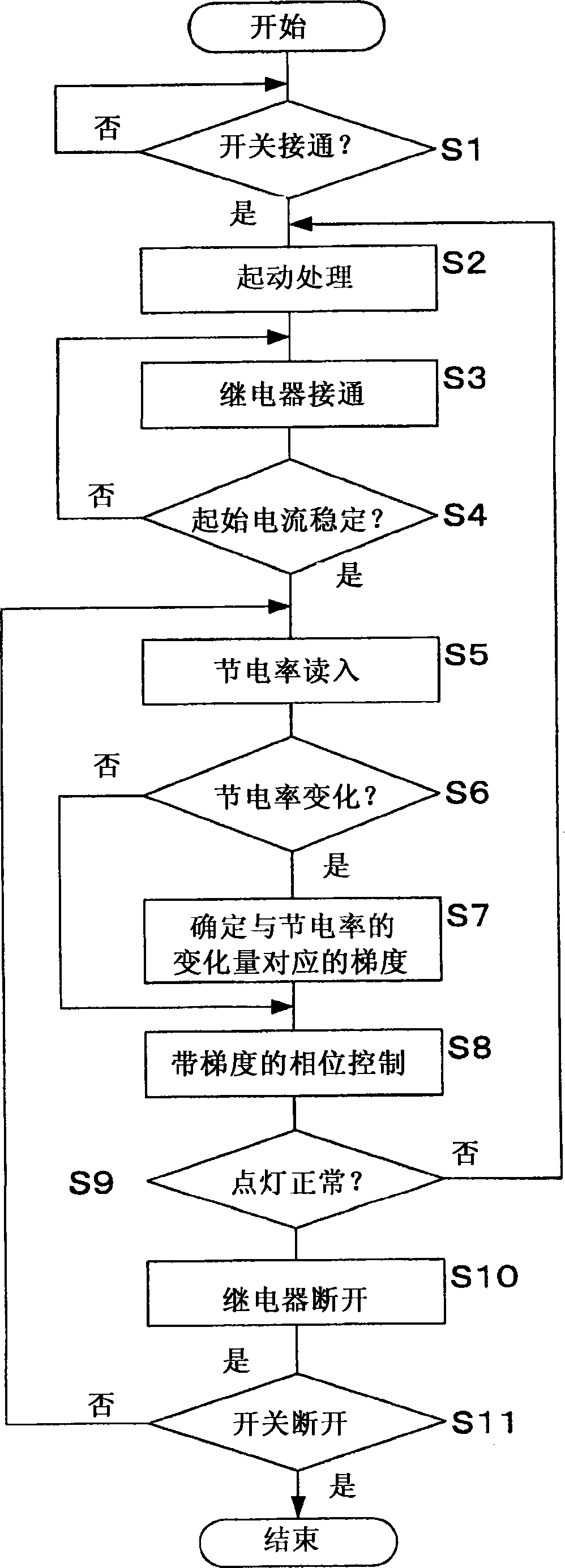
[0021] Between the AC power source 12 and the high-pressure discharge lamp 13 , a relay 20 is provided in parallel with the TRIAC 14 . The control circuit 18 turns on the relay 20 just after the high-pressure discharge la...


PUM


Abstract

The invention provides an energy-saving device for a high-pressure discharge lamp, and the energy-device performs energy saving of a high-pressure discharge lamp via a phase control of a power adjustment element, during change of energy-saving rate, poor lighting of the high-pressure discharge lamp will not be brought, and load of the power adjustment element caused by a startup current is reduced rightly after connection of a power source. The energy-saving device for a high-pressure discharge lamp comprises a TRIAC controlling power from an AC power to the high-pressure discharge lamp, a setting circuit setting an energy-saving rate, a zero-crossing circuit detecting a voltage wave form, and a storing circuit storing conducting timing sequence of TRIAC with respective to the voltage zero-crossing. Electrification of a relay is made rightly after power source conducting of a control circuit, and a phase control of TRIAC is started after stabilization of a startup current. During the phase control, the control circuit makes the conducting timing sequence change at a relatively steep gradient during small / big change of the energy-saving rate, preventing flickering and going-out of the high-pressure discharge lamp.

Description

technical field [0001] The invention relates to an electricity-saving device for reducing the power consumption of high-pressure discharge lamps such as mercury lamps and sodium lamps. Background technique [0002] Conventionally, there is known a device for reducing the power consumption of high-voltage discharge by controlling the turn-on timing of the power adjustment element. For example, the power saving device disclosed in Patent Document 1 is configured by providing a triac (TRIAC) as a power adjustment element between the AC power supply and the high pressure discharge lamp, and controlling the conduction of the TRIAC according to the power saving rate. timing, such as Figure 5 As shown, by stopping the arc discharge every half cycle of the voltage waveform, it is possible to save power corresponding to the waveform area of ​​the discharge stop period. [0003] Patent Document 1: JP Unexamined Publication No. 2009-277500 [0004] However, in existing power saving ...

Claims


Application Information

Patent Timeline
Patent Type & Authority Patents(China)
IPC IPC(8): H05B41/24H05B41/36
Inventor 加藤昌幸
Owner KAWAMURA ELECTRIC INC
Learn More