An ion plating arc spot control device and control method
The technology of a control device and control method, which is applied in the field of arc ion plating, can solve the problems of uneven target etching, large particle pollution of the film layer, and low utilization rate of the target, so as to reduce large particle pollution and control arc spot easily , the effect of fast movement speed
- Summary
- Abstract
- Description
- Claims
- Application Information
AI Technical Summary
Problems solved by technology
Method used
Image
Examples
Embodiment 1
[0037] Embodiment 1: An application example of the magnetic field structure and control method of the control device of the present invention on a large arc source with a target size of 160 mm.
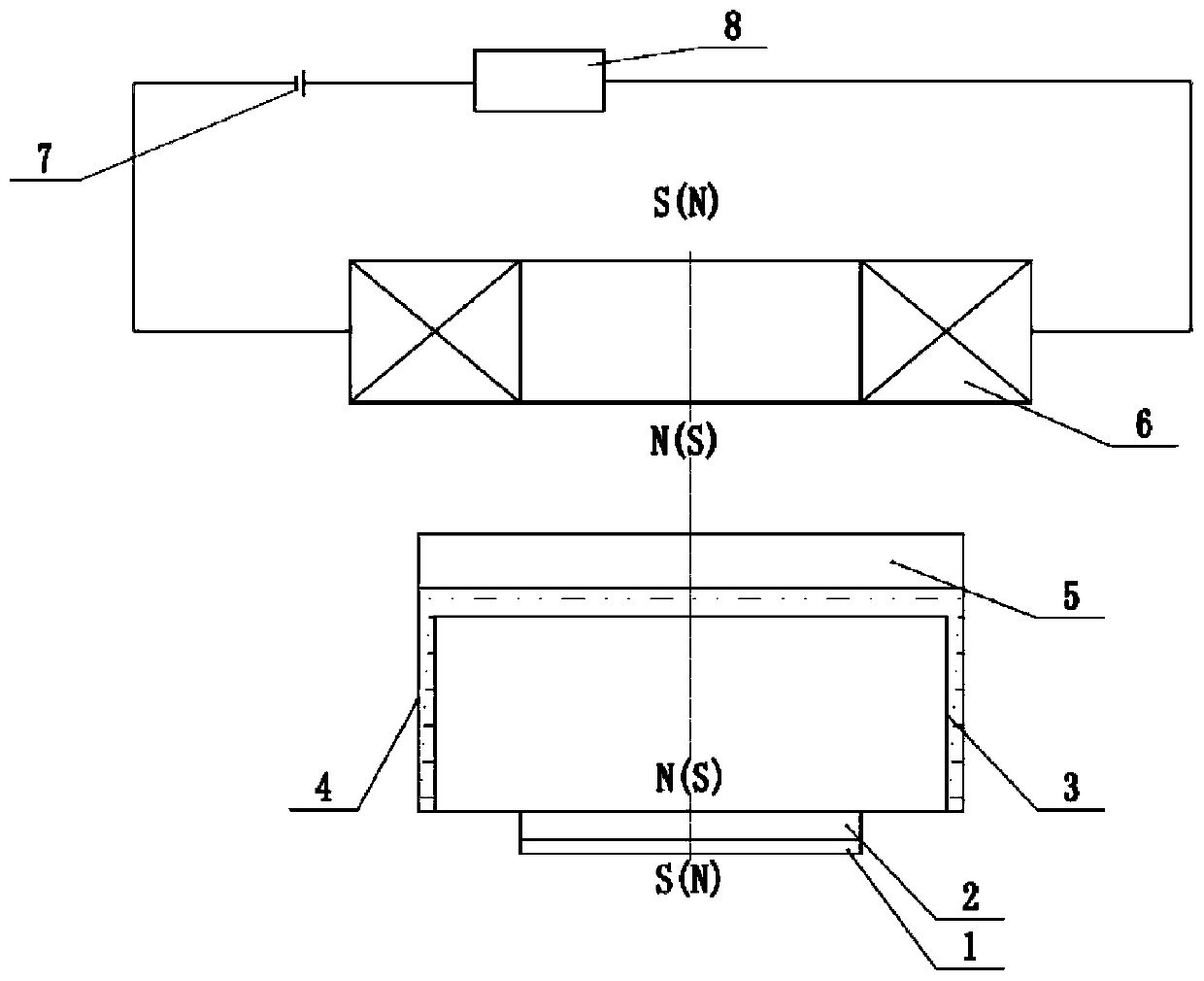
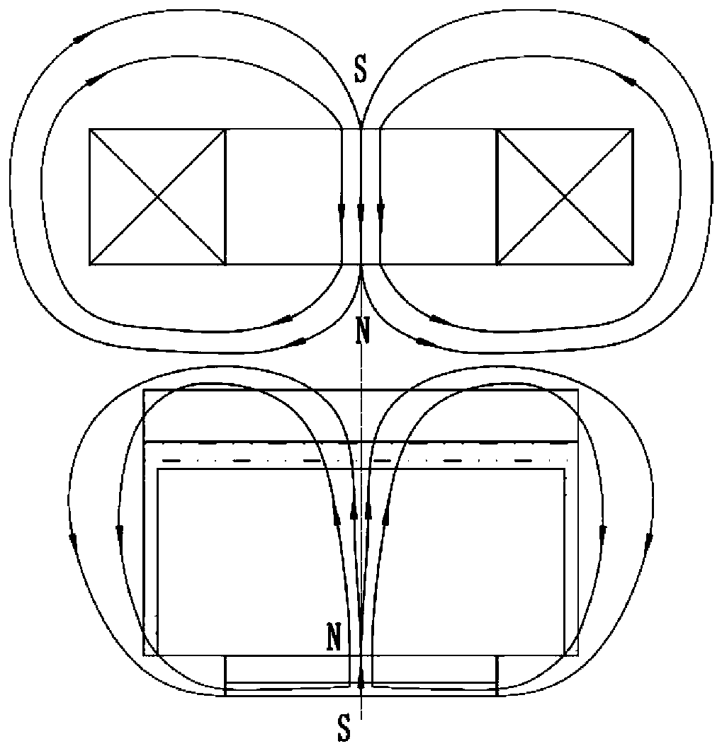
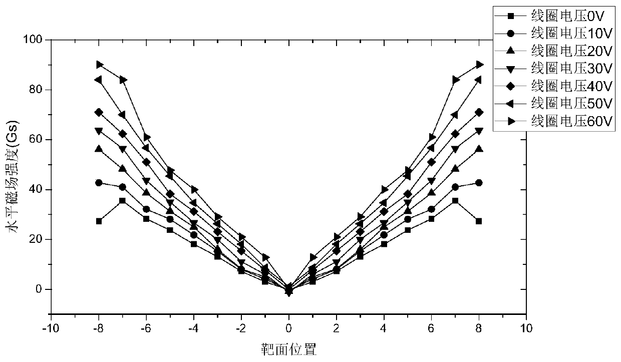
[0038] On the arc source whose target material is titanium and the size is 160mm, press figure 1 The magnetic field structure is arranged as shown, in which the N poles of all permanent magnet columns in the permanent magnet structure face the target surface, and the magnetic field generated by the permanent magnet structure passes through the target surface; the N poles of the magnetic field generated after the electromagnetic coil is energized face the target surface, and the magnetic field The induction line penetrates the target surface, and the electromagnetic field and the permanent magnetic field are coupled at the target surface. The schematic diagram of the magnetic field induction line is as follows: figure 2 shown. At this time, the axial component of the permanent magnet...
Embodiment 2
[0040] Embodiment 2: An example of the magnetic field structure of the control device of the present invention in maintaining arc discharge stability.
[0041] On the arc source with a target size of 160 mm, the magnetic field structure is installed and adjusted according to the requirements of this patent, and a CrAl alloy target is selected. By comparing the minimum current that the arc spot can stably discharge when only using the permanent magnetic field and the minimum current that the arc spot can stably discharge when the electromagnetic field and the permanent magnetic field are coupled to the magnetic field of the present invention, it shows that the axisymmetric coupled magnetic field arc source structure of the present invention can stabilize the arc discharge. aspects of the effect.
[0042] Experimental process: first pump the vacuum chamber to 1.5×10 -2 Pa, then feed nitrogen into the vacuum chamber to keep the pressure of the vacuum chamber at 1.8Pa. When the ...
Embodiment 3
[0043] Embodiment 3: the magnetic field structure and control method of the control device of the present invention, and an example of improving the coating quality.
[0044] The titanium nitride film is plated on the substrate, and the effect of the present invention on reducing the pollution of large particles and improving the quality of the film is demonstrated by comparing the quality of the plated film layer using the control method of the present invention and the static magnetic field method only.
[0045] Experimental process: After grinding and polishing the stainless steel substrate, it was ultrasonically cleaned with acetone and alcohol respectively for 20 minutes, and then dried and placed in a vacuum chamber. Evacuate to a vacuum of 3×10 -2 Pa, pass argon gas to 2.0Pa, turn on the bias voltage of 500V, and perform glow cleaning for 20min. Then pump down to 1.5×10 -2 Pa, the working pressure of feeding nitrogen reaches 1.0Pa, turn on the bias voltage of 200V, ig...
PUM
 Abstract
Description
Claims
Application Information
 - R&D
- Intellectual Property
- Life Sciences
- Materials
- Tech Scout
- Unparalleled Data Quality
- Higher Quality Content
- 60% Fewer Hallucinations
Browse by: Latest US Patents, China's latest patents, Technical Efficacy Thesaurus, Application Domain, Technology Topic, Popular Technical Reports.
© 2025 PatSnap. All rights reserved.Legal|Privacy policy|Modern Slavery Act Transparency Statement|Sitemap|About US| Contact US: help@patsnap.com


