
Three-roller multi-wire cutting machine

A multi-wire cutting machine and cutting roller technology, which is applied to fine working devices, stone processing equipment, manufacturing tools, etc., can solve problems such as bending and unstable cutting wire tension, and achieve high efficiency, stable cutting quality, and equipment volume small effect

Inactive Publication Date: 2011-10-12
黄禹宁
View PDF5 Cites 18 Cited by
  • Summary
  • Abstract
  • Description
  • Claims
  • Application Information

AI Technical Summary

Problems solved by technology

[0005] Since the auxiliary cutting roller is arranged in the middle of the two cutting rollers, the cutting area between the two cutting rollers is divided into two sections, and each cutting section can cut a polysilicon rod independently, so the cutting span of each cutting section can be Reduced to the minimum, it can effectively solve the phenomenon of unstable tension, bending and shaking of the cutting line caused by the large span of the cutting line during the cutting process

Method used


Image

  • Three-roller multi-wire cutting machine
  • Three-roller multi-wire cutting machine
  • Three-roller multi-wire cutting machine

Examples


Embodiment Construction

[0013] Such as Figure 4 , Figure 5 As shown, two cutting rollers 11, 12 and auxiliary cutting roller 13 are erected in parallel in the cutting chamber 71 respectively, and the surfaces of two cutting rollers 11, 12 and auxiliary cutting roller 13 are provided with wire grooves ( Figure 4 and 5 not shown), the auxiliary cutting roller 13 is arranged on the center of symmetry or above the center of symmetry of the two cutting rollers 11, 12, and supports the cutting line 3 between the two cutting rollers 11, 12, so that the auxiliary cutting roller 13 Two independent cutting areas are formed between the two sides and the two cutting rollers 11, 12, and the angle α between the cutting lines 31, 32 on both sides of the auxiliary cutting roller 13 and the plane 14 where the axes of the two cutting rollers are located is 0 In the range of °~30°, the included angle α is preferably in the range of 0°~15°; above the two cutting rollers 11 and 12, there are two sets of symmetricall...


PUM


Abstract

The invention relates to a three-roller multi-wire cutting machine used for cutting a wafer. The three-roller multi-wire cutting machine comprises two cutting rollers and one auxiliary cutting roller, wherein the two cutting rollers are arranged in a cutting chamber in parallel; the auxiliary cutting roller is arranged at or above the symmetric center of the two cutting rollers; each included angle alpha, which is formed between each of the two cutting lines at two sides of the auxiliary cutting roller and a plane in which the axis of the two cutting rollers are located, is 0-30 degrees; two operating platforms and two feeding systems are arranged; the operating platforms and the feeding systems are symmetrically arranged; and the straight guide rails of the two feeding systems are respectively vertical to the cutting lines at the two sides of the auxiliary cutting roller. The three-roller multi-wire cutting machine can be used for cutting two polycrystalline silicon rods at the same time. Besides, the cutting quality is stable, the machine volume is small, the cost is low, the efficiency is high, and the cutting production cost is lowered.

Description

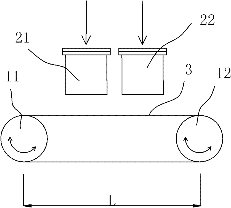
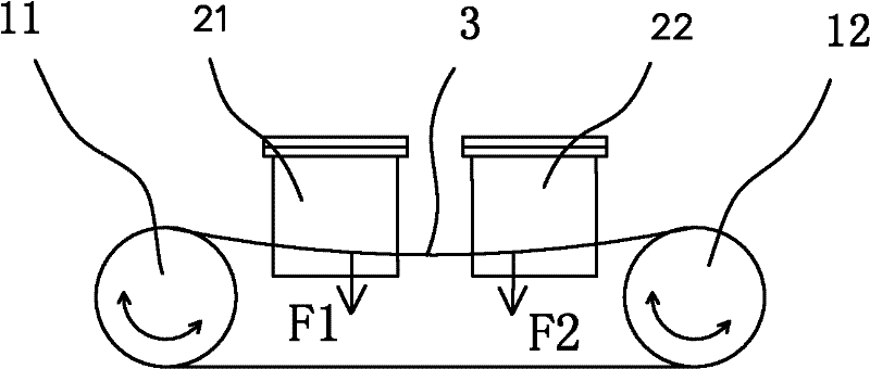
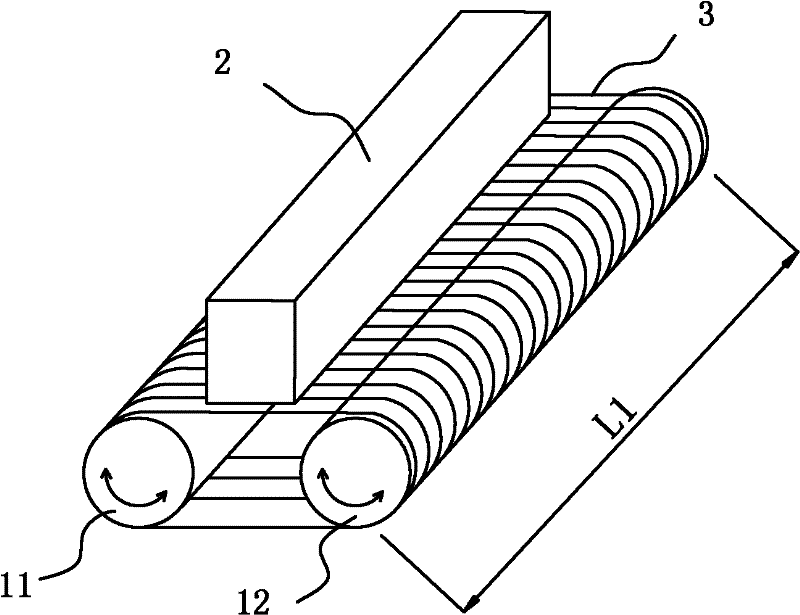
technical field [0001] The invention relates to a multi-wire cutting machine for cutting wafers, in particular to a three-roller multi-wire cutting machine. Background technique [0002] At present, solar-grade silicon wafers and sapphire substrates for LEDs are produced on a large scale using multi-wire cutting machines. figure 1 Shown is the cutting principle diagram of the current NTC MWM442DM model in Japan. Multiple cutting lines 3 are wound on two parallel cutting rollers 11 and 12, and the workpieces 21 and 22 are driven downward by the workbench to meet the cutting rollers 11 and 12 The adjustment movement between the 3 contacts of the cutting line is cut into pieces. This structure can cut two monocrystalline silicon rods at the same time. When cutting two polycrystalline silicon rods, since the hardness of polycrystalline silicon is slightly harder than that of monocrystalline silicon and is not uniform enough, the span L between the two cutting rollers is too lar...

Claims


Application Information

Patent Timeline
Patent Type & Authority Applications(China)
IPC IPC(8): B28D5/04
Inventor 黄禹宁刘宇宁潘勇涛
Owner 黄禹宁
Learn More