Waste oil smelting exhaust gas back-burning device

A waste gas and back-burning tube technology, which is applied in the direction of combustion method, combustion type, lighting and heating equipment, etc., can solve the problems of easy explosion and air pollution, and achieve the effect of saving energy and avoiding air pollution

Inactive Publication Date: 2011-10-12
KAI COUNTY SHUANGXING RENEWABLE ENERGY
View PDF6 Cites 1 Cited by
  • Summary
  • Abstract
  • Description
  • Claims
  • Application Information

AI Technical Summary

Problems solved by technology

[0003] Waste oil smelting mainly includes steps such as high-temperature heating—fractionation in a fractionating tower—condensation of oil and gas—and oil-forming treatment. Since the oil and gas from the fractionating tower are condensed, there is still a small amount of flammable non-condensable gas. If the non-condensable gas does not pass through If it is directly discharged into the atmosphere, it will pollute the atmosphere. In addition, the non-condensable gas is a combustible gas, and it is easy to cause safety accidents such as explosions when discharged in a small space.

Method used


Image

  • Waste oil smelting exhaust gas back-burning device
  • Waste oil smelting exhaust gas back-burning device
  • Waste oil smelting exhaust gas back-burning device

Examples


Embodiment 1

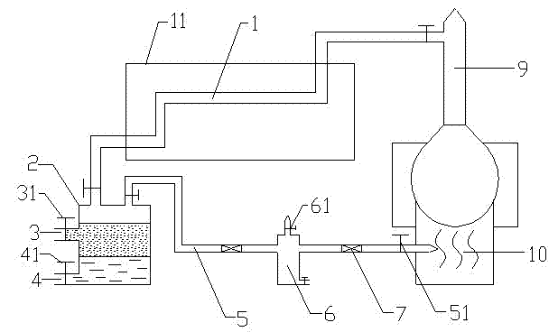
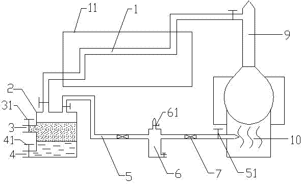
[0017] Embodiment 1, the waste oil smelting waste gas back-burning device of the present invention includes a separation cabinet 2 connected to the condensing oil outlet pipe 1, an oil outlet 3 and a water outlet 4 are arranged on the separation cabinet, and oil outlets and water outlets are respectively provided with oil outlet valves 31 and the water outlet valve 41 also include a waste gas back-burning pipe 5, one end of the waste gas back-burning pipe communicates with the top of the separation cabinet, and the other end communicates with the hearth of the oil refining furnace, and the waste gas back-burning pipe is provided with a waste gas control valve 51 near the end of the oil refining furnace. During oil refining, high-temperature oil and gas come out of the fractionating tower 9 and enter the condensate oil outlet pipe 1. The middle section of the condensate oil outlet pipe 1 is located in the cooling pool 11. After condensation, semi-finished oil is generated and ent...

Embodiment 2

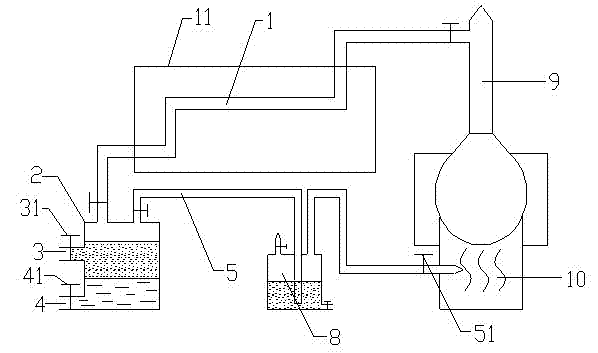
[0020] Embodiment 2. The difference between this embodiment and Embodiment 1 lies in the different designs of the anti-tempering device. In this embodiment, the anti-tempering device includes a flame-retardant cabinet 8, which contains water and waste gas back-burning pipes One end of the air intake is arranged under the water surface. The non-condensable gas enters the flame-retardant cabinet through the water surface of the flame-retardant cabinet 8 filled with water, and then enters the furnace, and the tempering phenomenon occurs in time. When the tempering reaches the flame-retardant cabinet 8, due to the barrier effect of the water in the flame-retardant cabinet , to prevent the tempering from continuing to spread to the end of the separation cabinet, so it will not lead to safety accidents.

[0021] As a further improvement to the above two embodiments, a pressure relief valve 61 is also provided on the top of the secondary separation cabinet 6 . When the refining furn...


PUM


Abstract

The invention discloses a waste oil smelting exhaust gas back-burning device. The device comprises a separation cabinet communicated with a condensation oil outlet pipe, wherein an oil outlet and a water outlet are arranged on the separation cabinet; and an oil outlet valve and a water outlet valve are arranged on the oil outlet and water outlet respectively. The device also comprises an exhaust gas back-burning pipe, wherein one end of the exhaust gas back-burning pipe is communicated with the top of the separation cabinet, and the other end is communicated with a hearth of an oil smelting furnace; and an exhaust gas control valve is arranged at the end close to the oil smelting furnace, of the exhaust gas back-burning pipe. As an exhaust gas back-burning device is additionally arranged in the oil smelting system, a small amount of non-condensable gas can be separated and introduced to be burnt in the hearth of the oil smelting furnace and recycled, thereby saving energy, avoiding atmospheric pollution caused by direct discharge, and protecting environment.

Description

technical field [0001] The invention relates to a waste gas treatment device, in particular to a burnback device for non-condensable gas in the waste oil smelting process. Background technique [0002] With the rapid development of society, the demand for various energy sources is increasing day by day, especially the demand for power energy such as oil is huge. With the vigorous exploitation of human beings, resources are increasingly scarce. At the same time, with the continuous pollution of the environment by human beings, environmental protection has become a common problem faced by all human beings. With the development of science and technology, waste oil smelting recycling technology is becoming more and more mature, and energy saving and environmental protection are strongly advocated. One of the main methods of waste oil regeneration is through the smelting-fractionation method, through the heating and smelting of waste oil and other raw materials, and then fractio...

Claims


Application Information

Patent Timeline
Patent Type & Authority Applications(China)
IPC IPC(8): F23G7/06
Inventor 陈兴学陈豪
Owner KAI COUNTY SHUANGXING RENEWABLE ENERGY
Why Eureka
Try Eureka