Laser speckle eliminating device with dodging function

A laser speckle and optical function technology, applied in optics, optical components, instruments, etc., can solve the problem of unimproved beam non-uniformity

Inactive Publication Date: 2013-07-03
XIAN UNIV OF POSTS & TELECOMM
View PDF8 Cites 0 Cited by
  • Summary
  • Abstract
  • Description
  • Claims
  • Application Information

AI Technical Summary

Problems solved by technology

The disadvantage of this method is that the structure of the laser itself needs to be changed, and the beam inhomogeneity of the laser beam itself has not been improved.

Method used


Image

  • Laser speckle eliminating device with dodging function
  • Laser speckle eliminating device with dodging function
  • Laser speckle eliminating device with dodging function

Examples


Embodiment Construction

[0018] The present invention will be described in detail below in conjunction with specific embodiments.

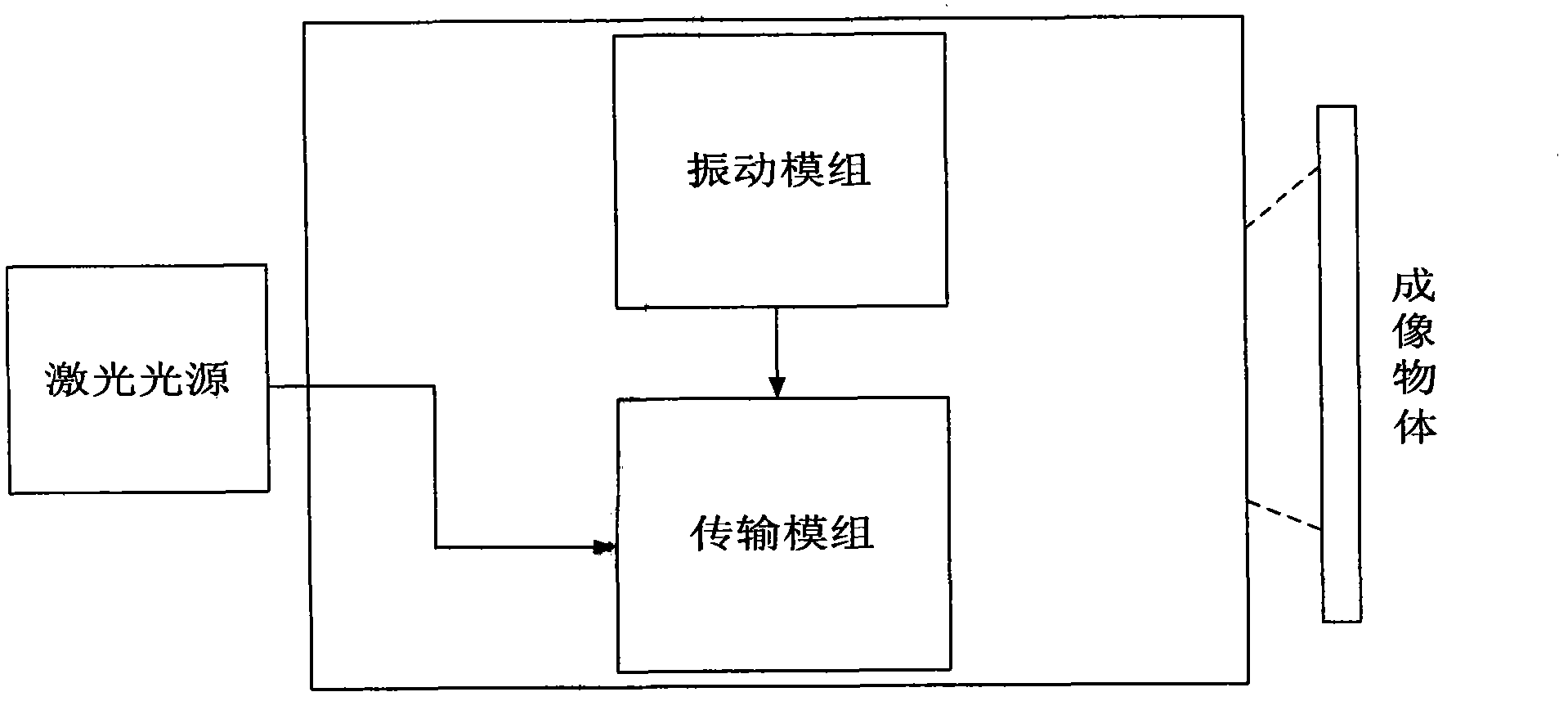
[0019] figure 2 It is a structural schematic diagram of the laser speckle elimination device with uniform light function of the present invention, including a laser light source, a transmission medium, a vibration module, and the vibration module is fixedly connected to the transmission medium.

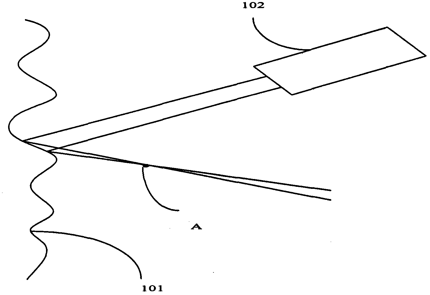
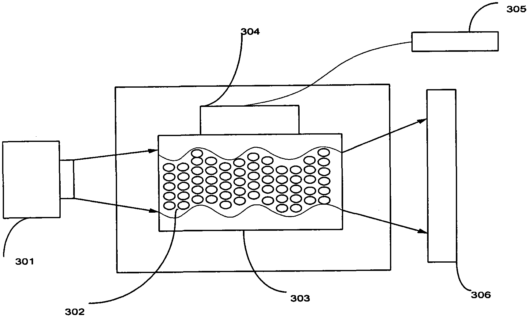
[0020] image 3 It shows the internal structure diagram and optical path schematic diagram of the present invention, wherein the laser beam 301 emitted by the laser light source is transmitted through the transmission medium 303 with the scatterer 302 inside, and the scatterer 302 is made of a material different from the transmission medium 303 and is distributed with a uniform density In the transmission medium, under normal circumstances, the transmission medium 303 can be made of polymethyl methacrylate, while the scatterer 302 mostly uses 4 μm SiO with a mass fraction of 0....


PUM


Abstract

The invention discloses a laser speckle elimination device with uniform light function, which comprises a laser light source, a transmission medium, a vibration module, and the vibration module is fixedly connected to the transmission medium. There is a scatterer in the transmission medium, and the scatterer is composed of Materials different from the transmission medium are formed in the transmission medium with a uniform density distribution; the vibration module vibrates under the action of the power supply, and then drives the transmission medium and the scatterer to vibrate together, and the input power of the vibration module is adjusted to To adjust the vibration amplitude of the transmission medium and the scatterer until the best speckle removal effect is obtained.

Description

Technical field [0001] The present invention involves a laser scattering removal device with uniform light function, which is a laser imaging technology field. Background technique [0002] The laser has the characteristics of good direction, high brightness, good monochrome, and good coherent characteristics. It is these characteristics that make the laser application in various fields.However, because the laser is particularly good, the scattered noise will be formed in the imaging, which affects the quality of the imaging and needs to be controlled.In the typical hollow rectangular strong laser beams of the laser output, the intensity distribution of the beam along the flow field is not uniform.The submissiveness of the light strength will cause uniform thermal deformation in the many reflex mirrors in the internal transmission channel of the laser, which causes the laser system to eventually output the front distribution of the beam of the beam, resulting in a decrease in the...

Claims


Application Information

Patent Timeline
Patent Type & Authority Patents(China)
IPC IPC(8): G02B27/48G02B27/09
Inventor 贺锋涛
Owner XIAN UNIV OF POSTS & TELECOMM
Why Eureka
Try Eureka