Thermostatic equipment and control method thereof

A constant temperature equipment and equipment technology, which is applied in the direction of using electric mode for temperature control, auxiliary controller with auxiliary heating device, etc., can solve the problem of cumbersome and unsuccinct control method of control system, difficult to achieve better control accuracy and production cost. Advanced problems, to achieve the effect of simple and effective control method, reduced processing cost and processing requirements, and simple structure

Active Publication Date: 2011-10-12
SUZHOU JIEMEI ELECTRONICS
View PDF4 Cites 17 Cited by
  • Summary
  • Abstract
  • Description
  • Claims
  • Application Information

AI Technical Summary

Problems solved by technology

The constant temperature equipment is mainly composed of a cabinet, a heating system, a refrigeration system, an air circulation system and a control system. In addition, the control method of the control system is cumbersome and not simple, and it is difficult to achieve better control accuracy.

Method used


Image

  • Thermostatic equipment and control method thereof
  • Thermostatic equipment and control method thereof
  • Thermostatic equipment and control method thereof

Examples


Embodiment

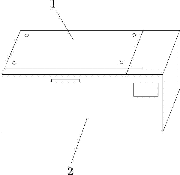
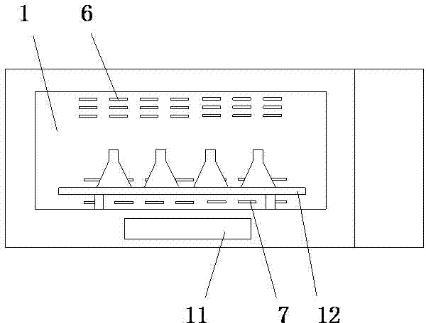
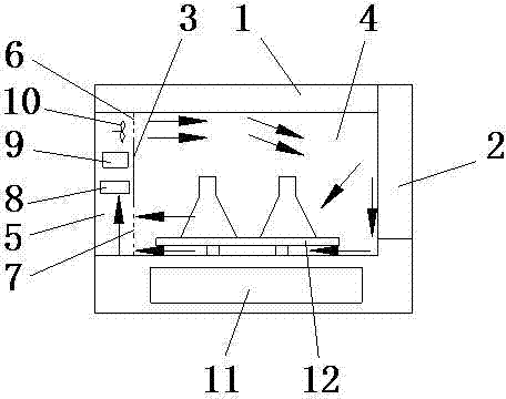
[0034] like Figure 1 to Figure 3 As shown, a constant temperature oscillator includes a box body 1 with a control system and an oscillation mechanism 11 and a box door 2, and a working chamber 4 and an air duct 5 are formed in the cavity of the box body 1 through a partition plate 3, The air duct 5 is located at the rear of the working chamber 4, the bottom of the working chamber 4 is provided with a rocking plate 12, and the rocking plate 12 is driven to vibrate by the oscillating mechanism 11. The air inlet 6 of the air passage 5 and the working chamber 4, the lower part of the dividing plate 3 is evenly distributed with a plurality of air outlet holes 7 for connecting the air passage 5 and the working chamber 4, and the air passage 5 is sequentially arranged from bottom to top. There is a refrigeration system 8, a heating system 9 and a fan 10. In this embodiment, the refrigeration system 8 is an evaporator, and the heating system 9 is a heating pipe.

[0035] When the co...


PUM


Abstract

The invention discloses thermostatic equipment. In the equipment, an air passage is arranged in the back of a cavity and is sequentially equipped with a refrigerating system, a heating system and a fan from bottom to top, wherein wind blown from the fan flows towards an operating cavity via an air inlet, then returns to the air passage via an air outlet from the operating cavity after being bounced by a box door, and finally enters the operating cavity through the refrigerating system, the heating system and the fan so as to form one cycle. The thermostatic equipment can achieve better temperature uniformity only by virtue of the simple air channel structure, thus the structure of the equipment is simple and the processing cost and processing requirements are lowered. The invention further provides a method for controlling the thermostatic equipment. The method has the beneficial effects that parameters can be set as required; and by utilizing the method, the heating system and the refrigerating system are respectively controlled and meanwhile the temperature in the operating cavity is cooperatively controlled so that the temperature in the operating cavity is approximate to an expected temperature as far as possible. Therefore, the control method is simple and effective and can be used for greatly lowering the debugging requirement.

Description

technical field [0001] The invention relates to a constant temperature device and a control method thereof. Background technique [0002] The constant temperature equipment is mainly used to conduct environmental simulation tests on the physical and other related characteristics of the product in accordance with national standards or user-defined requirements under low temperature, high temperature, and conditions. After the test, the performance of the product is judged by inspection. Whether it can still meet the predetermined requirements, so as to be used for product design, improvement, appraisal and factory inspection. The constant temperature equipment is mainly composed of a cabinet, a heating system, a refrigeration system, an air circulation system and a control system. In addition, the control method of the control system is cumbersome and not simple, and it is difficult to achieve better control accuracy. Contents of the invention [0003] The object of the p...

Claims


Application Information

Patent Timeline
Patent Type & Authority Applications(China)
IPC IPC(8): G05D23/30
Inventor 陈志明杨强顾马强张永罡
Owner SUZHOU JIEMEI ELECTRONICS
Why Eureka
Try Eureka