Novel rotor lamination structure

A rotor punching, a new type of technology, applied in the field of punching structure, can solve the problems of increasing the difficulty in the development and design of motor controllers, difficult back electromotive force, etc., and achieve the effects of large reluctance torque, high mechanical strength, and high efficiency

Inactive Publication Date: 2011-10-12
TIANJIN SANTROLL ELECTRIC AUTOMOBILE TECH CO LTD
View PDF4 Cites 9 Cited by
  • Summary
  • Abstract
  • Description
  • Claims
  • Application Information

AI Technical Summary

Problems solved by technology

However, in the existing built-in structure, the back electromotive force waveform is usually a rectangular wave or a trapezoidal wave, and it is difficult to generate a back electromotive force with a sinusoidal waveform, which virtually increases the difficulty in the development and design of the motor controller.

Method used


Image

  • Novel rotor lamination structure
  • Novel rotor lamination structure
  • Novel rotor lamination structure

Examples


Embodiment Construction

[0010] The present invention will be further described below in conjunction with accompanying drawing and specific embodiment:

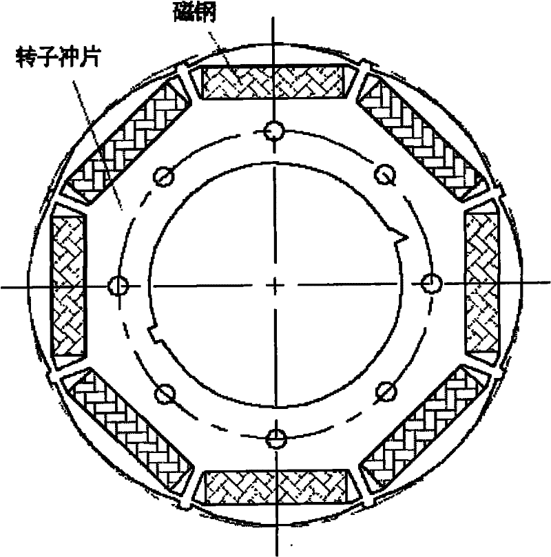
[0011] like figure 1 , When designing the rotor, the magnetic steel is embedded in the magnetic steel slot of the rotor core, and there are triangular slot gaps at both ends of the magnetic steel slot.

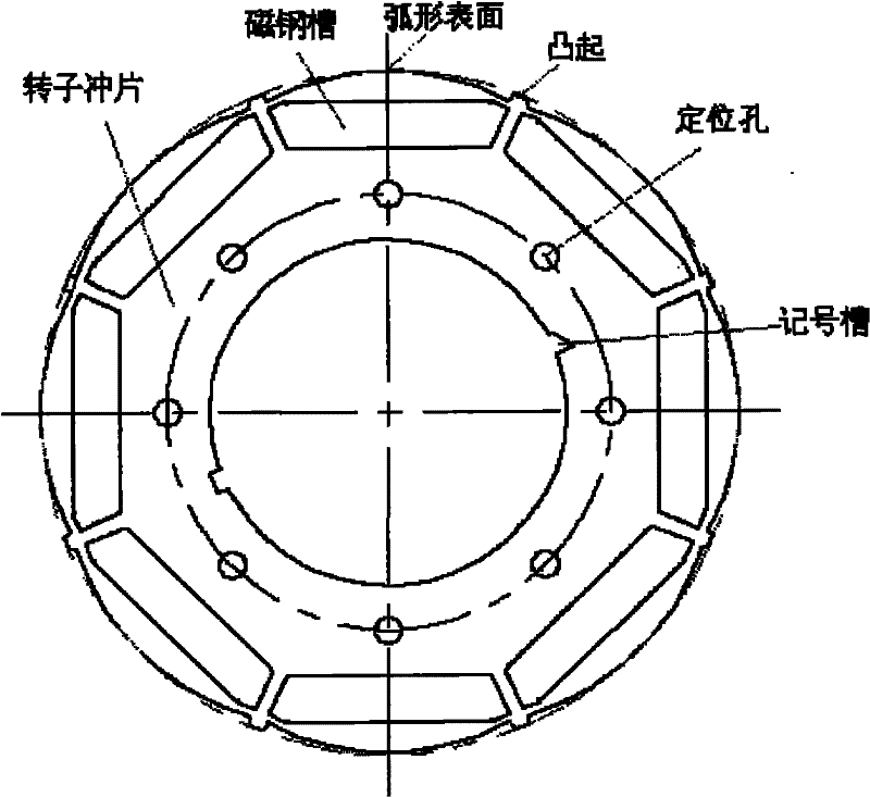
[0012] like figure 2 , its outer surface is an arc-shaped surface structure with eight sections evenly distributed. The position corresponding to the middle of the magnetic steel slot is the highest point of the arc-shaped surface; a bump. This structure can not only ensure that the rotor has sufficient mechanical strength at a relatively high speed, but also easily generate a back electromotive force with a sinusoidal waveform. In addition, eight positioning holes are evenly distributed in the middle part of the rotor punch; on the inner circle of the punch, there are a pair of marking grooves.

[0013] Utilize the technical solution described ...


PUM


Abstract

The invention relates to a novel rotor lamination structure which has the advantages of a surface type rotor magnetic path structure and a built-in type rotor magnetic path structure. The outer surface of the rotor lamination structure has eight uniformly distributed cambered surface structures; corresponding positions on the middle parts of magnetic steel slots are the highest points of cambered surfaces; and eight bulges are uniformly distributed at positions corresponding to gaps in the middle of every two adjacent magnetic steel slots. The novel rotor lamination structure can easily produce a back electromotive force with sine waveform, has high mechanical strength and a larger saliency ratio and is convenient for flux weakening speed expansion.

Description

technical field [0001] The invention belongs to the field of permanent magnet synchronous motors and relates to a punching structure of a novel rotor. Background technique [0002] Now commonly used permanent magnet synchronous motor rotor magnetic circuit structure is generally divided into surface type and built-in type. For the surface rotor magnetic circuit structure, the permanent magnets are usually tile-shaped and located on the outer surface of the rotor core, and the direction in which the permanent magnets provide magnetic flux is radial. Although this kind of rotor magnetic circuit structure is easy to generate back electromotive force with sinusoidal waveform, which is convenient for the research and development and design of the speed-regulating permanent magnet synchronous motor controller, but when running at high speed, the centrifugal force is very large, and it needs to be protected on the outer surface of the rotor. Non-magnetic sleeve, which greatly incr...

Claims


Application Information

Patent Timeline
Patent Type & Authority Applications(China)
IPC IPC(8): H02K1/27
Inventor 余国权孔昭松
Owner TIANJIN SANTROLL ELECTRIC AUTOMOBILE TECH CO LTD
Why Eureka
Try Eureka