
Automated analysis device with an automatic pipetting device and two pump units of different capacities

An automatic analysis device and pumping technology, applied in the direction of analysis materials, measuring tubes/pipettes, laboratory utensils, etc., can solve the problems of insufficient piston displacement, a large number of moving wear parts, large space of the analyzer, etc. Moving and wear parts, space saving effect

Inactive Publication Date: 2011-10-12
DIASYS TECH R L
View PDF4 Cites 4 Cited by
  • Summary
  • Abstract
  • Description
  • Claims
  • Application Information

AI Technical Summary

Problems solved by technology

Typically, metered syringes designed for small volumes have insufficient piston displacement to perform a flush cycle quickly
[0009] These pumping units have a very expensive construction, a large number of moving wear parts and take up a relatively large amount of space within the analyzer

Method used


Image

  • Automated analysis device with an automatic pipetting device and two pump units of different capacities
  • Automated analysis device with an automatic pipetting device and two pump units of different capacities
  • Automated analysis device with an automatic pipetting device and two pump units of different capacities

Examples


Embodiment Construction

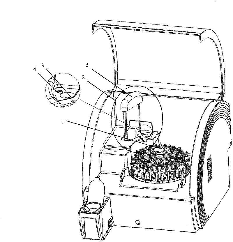
[0034] figure 1 A device for automatic analysis of liquids (analyzer) is shown, which has a carousel 1 for liquid containers and a pipetting device 2 with a pipetting arm 5 . The carousel 1 is arranged such that it can introduce liquid containers into the working area of ​​the pipetting arm 5 . Furthermore, a rinsing station 3 and a measuring device 4 for determining the exact position of the pipetting needle tip are also arranged in the working area of ​​the pipetting arm 5 .

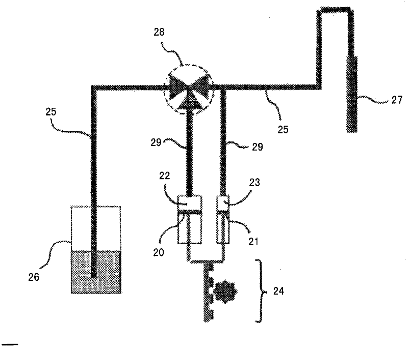
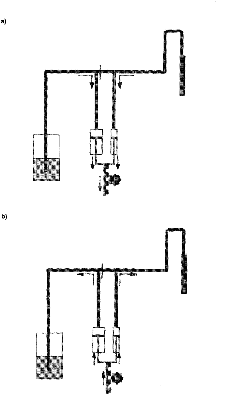
[0035] figure 2 A schematic diagram showing a suction system according to the invention with two pumping units of different capacities. The pumping unit is formed by pistons 20 , 21 which are arranged axially movable in the cavity. In each case, the two pistons 20 , 21 delimit together with the cavity a working chamber 22 , 23 whose volume varies with the axial position of the pistons 20 , 21 . The left piston 20 is a large piston which moves in a correspondingly large cavity and thus delimits a c...


PUM


Abstract

The invention relates to an automatic pipetting device comprising at least two pump units of different capacities and a liquid line, said liquid line opening into a rinse liquid reservoir on one side and to a pipetting needle on the other side. In order to allow one pump unit to carry out a pipetting cycle at low volumes at high stroke resolutions and to allow the other pump unit to carry out a rinse cycle at large volumes, and in order to adapt the pump units to be as space-saving, low-maintenance and cost-effective as possible in the process, the invention proposes that the pistons of the at least two pump units are driven synchronously by a piston drive device, and that the position at which the largest working chamber is connected to the liquid line is disposed closer to the rinse liquid reservoir than the position at which the working chamber of the at least one other pump unit is connected to the liquid line, wherein a 3-way valve is also disposed at the liquid line at the point at which the largest working chamber is connected to the liquid line.

Description

technical field [0001] The invention relates to an automatic liquid suction device of a device for automatic analysis of liquids, wherein the liquid suction device comprises at least two pumping units with different capacities and liquid pipelines, wherein each pumping unit has a cavity, each cavity Axially movable pistons are arranged inside, wherein each piston defines a working chamber together with the cavity in which the piston is arranged, and the volume of the working chamber varies with the axial position of the piston, wherein the piston passes through the rear race The drive means are moved axially, wherein each working chamber is connected to a liquid line, which on one side opens into the flushing fluid reservoir and on the other side has a transition to the aspiration needle. Furthermore, the invention relates to an automatic analysis device having such an automatic pipetting device. Background technique [0002] In the context of increasing automation in the f...

Claims


Application Information

Patent Timeline
Patent Type & Authority Applications(China)
IPC IPC(8): B01L3/02
CPCB01L3/022B01L2200/0621G01N35/10G01N35/1004G01N35/1016
Inventor R·塞恩基
Owner DIASYS TECH R L
Learn More