

Method and apparatus for generating a carrier frequency signal
一种载频信号、频率信号的技术,应用在通信领域,能够解决限制调制带宽等问题,达到增加匹配度、增加精确性、快速信道跳频的效果
- Summary
- Abstract
- Description
- Claims
- Application Information
AI Technical Summary
Problems solved by technology
Method used
Image

Examples
Embodiment Construction
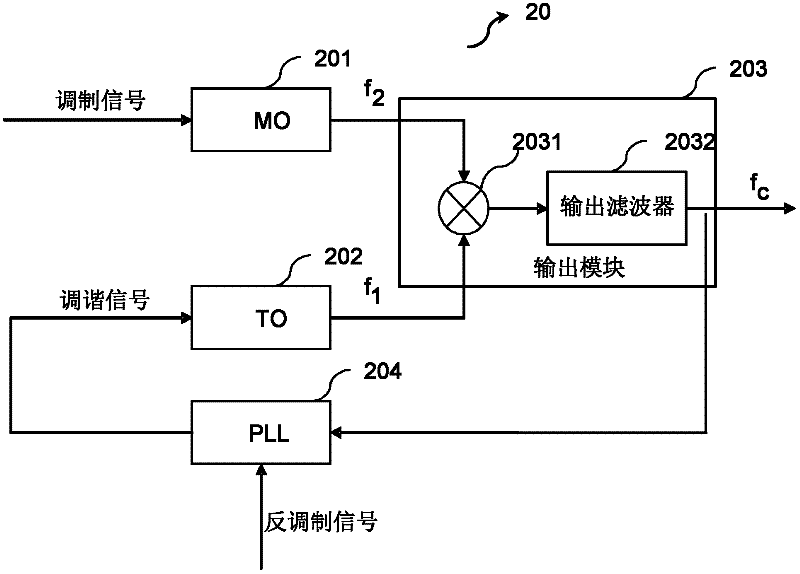
[0054] To avoid the problem of low bandwidth, a two-point modulation structure can also be used, where the modulating signal is inserted at one point to modulate the output loop (PLL) and reversed into the loop feedback path so that no modulation occurs in the loop .
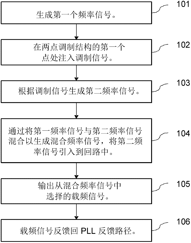
[0055] Refer below figure 1 An embodiment of the invention is described showing a method of generating a carrier frequency signal in a two-point modulation structure.
[0056] Step 101: Generate a first frequency signal.
[0057] The first frequency signal can be expressed as f 1 .
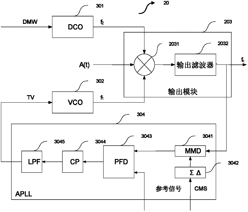
[0058] This embodiment may include generating the first frequency signal from a digital tuning word (DTW), or generating a first frequency signal from a tuning voltage (TV) (depending on whether a digitally controlled oscillator (DCO) or a voltage controlled oscillator (VCO) is used VCO)). DTW or TV is the output of the PLL.
[0059] Another problem encountered is that oscillator dragging and injection locking can cause spuri...
PUM
 Abstract
Description
Claims
Application Information