Processing method of twisted guide rail

A processing method and technology of guide rails, which are applied in the directions of track contact elements, railway car body parts, transportation and packaging, etc., can solve the problem that the size of the L-shaped flange of the slide rail cannot be guaranteed, the grinding of the corrugated surface cannot be realized, and the mechanical deformation is large. and other problems, to achieve the effect of significant cost saving, high yield and qualified acceptance

Inactive Publication Date: 2013-06-12
TIANJIN SERI MACHINERY EQUIP
View PDF5 Cites 0 Cited by
  • Summary
  • Abstract
  • Description
  • Claims
  • Application Information

AI Technical Summary

Problems solved by technology

[0005] The length-to-width ratio of this slide rail is about 25:1, and the rigidity is poor. Since the sliding surface at the bottom of the slide rail is a six-section corrugated surface, if the amount of grinding after quenching is reserved, neither the vertical axis circular table grinder nor the rectangular table surface grinder can achieve the grinding of the corrugated surface. , if it is processed before quenching, the hardened surface is semi-circular C-shaped, and semi-circular induction hardening is required to retain the non-hardened surface. The deformation of heat treatment and machining is large, and the size of the L-shaped flange of the slide rail cannot be guaranteed to be 22.5 +0.10 and 300 -0.2 , in other words, there is currently no mature and effective processing scheme for this kind of foreign design to produce the designed product
[0006] Each small trolley uses four such slide rails, and 45 custom-made small trolleys use a total of 180 slide rails, and an additional one is used for destructive experiments during hardness testing. The production batch is large, and the process method directly determines the difficulty of production. , the cost needs to be carefully considered

Method used


Image

  • Processing method of twisted guide rail
  • Processing method of twisted guide rail
  • Processing method of twisted guide rail

Examples


Embodiment Construction

[0029] In order to further understand the invention content, characteristics and effects of the present invention, the following examples are given, and detailed descriptions are as follows in conjunction with the accompanying drawings:

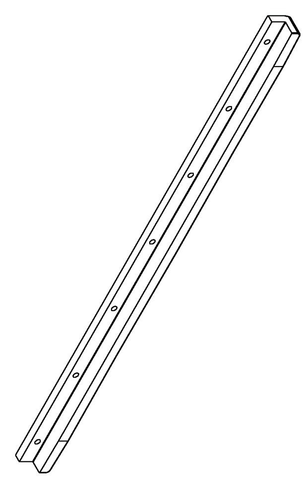
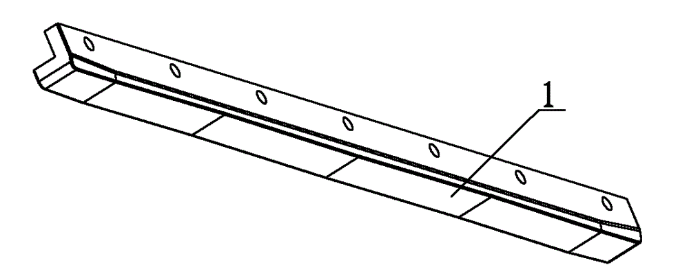
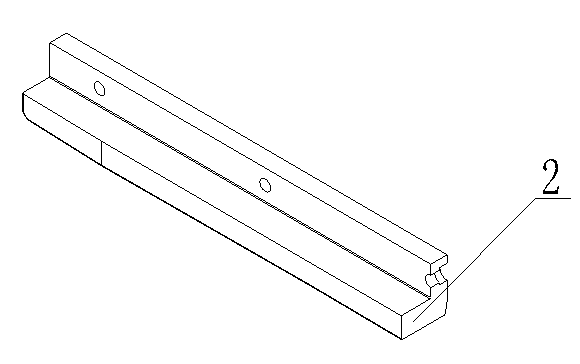
[0030] see Figure 1 to Figure 5 ,

[0031] The action principle of the present invention is:

[0032] 1. The forging material is a rectangular strip blank of 42CrMo, which is inspected according to the level IV of JB / T5000.8-07;

[0033] 2. The rough machining of the blank to the shape of 70×80×1500 (mm), the L-shaped surface has a 5mm allowance on one side, and the roughness of all surfaces reaches 6.3. During processing, such as Figure 4 , Figure 5 , keep the iron meat at the design reinforcement;

[0034] 3. Quenching and tempering HB310-350 and cleaning the surface of the workpiece;

[0035] 4. For tire fitting orthopedics, the straightness is within 2mm;

[0036] 5. Non-destructive testing: Ultrasonic, tensile strength and hardn...


PUM


Abstract

The invention relates to a processing method of a twisted guide rail. A cross section of the twisted guide rail is L-shaped; the lower surface of the twisted guide rail consists of a horizontal area and a plurality of sections of continuous inclined planes. The processing method comprises the steps of: a, adopting a forgeable piece as a blank; b. performing coarse processing, processing a reinforcing rib by making use of the material on the forgeable piece when performing coarse processing; c, after finishing the coarse processing, performing a hardening and quenching work procedure, a tire matching and shape righting work procedure and a nondestructive testing work procedure of a semi-finished product; d, semi-finish machining and straightening workpieces; e. finish machining: machining all of the surfaces into a finished-product dimension, retaining the reinforcing rib; f, surface quenching: sensing and heating by adopting semi-circle; g, removing the reinforcing rib, grinding and polishing; and h, performing nondestructive testing. The processing method is suitable for processing a slender slide rail that has a large length-width ratio, a surface quenching hardness HRC of 50-56, a tensile strength Rm of 1000-1150N / mm<2>, a cross section of an unstable geometrical shape and a sliding surface of a twisted surface.

Description

technical field [0001] The invention belongs to the field of mechanical processing, and in particular relates to a processing method of a zigzag slide rail. Background technique [0002] The form of the slide rail used for the small pulley in the roller table part of the steelmaking equipment designed abroad is relatively special. The feature is that the workpiece is slender and the cross-sectional geometry is unstable. The material of the slide rail is generally forging, alloy steel, etc., which are relatively expensive and require high internal performance and surface hardness, that is, multiple heat treatments need to be interspersed during the processing. [0003] For the above-mentioned workpieces, the traditional process plan is: steel plate blank - rough machining - semi-finishing (reserved grinding amount) - surface quenching - grinding. The problem is that the internal stress of the workpiece is large, the amount of metal removed by rough machining is large, and th...

Claims


Application Information

Patent Timeline
Patent Type & Authority Patents(China)
IPC IPC(8): B61F11/00
Inventor 王泉祥朱惠
Owner TIANJIN SERI MACHINERY EQUIP
Why Eureka
Try Eureka