Chain-transmission belt conveyer

A technology of belt conveyor and chain drive, which is applied in the direction of conveyors, conveyor objects, transportation and packaging, etc. It can solve problems such as slowing down or staying in place, large errors in detection results, and equipment safety accidents. The conveyor belt is slippery, the installation is convenient and quick, and the modification cost is low

Active Publication Date: 2011-10-19
ANSTEEL GRP MINING CO LTD
View PDF5 Cites 9 Cited by
  • Summary
  • Abstract
  • Description
  • Claims
  • Application Information

AI Technical Summary

Problems solved by technology

This kind of belt conveyor generally includes a driving mechanism, a driving roller (head wheel), a supporting wheel, a rotary wheel (tail wheel), a conveyor belt, etc. ) and the conveyor belt to transmit power, due to the deflection of the feeding point for the belt conveyor, the eccentric impact of the bottom mineral material on the conveyor belt, the deviation of the installation angle of the head and tail wheels, etc., the belt conveyor The conveyor belts frequently run off and misplaced, resulting in the phenomenon of material being spilled during the transportation process.
Even if a nuclear detector is installed in individual parts, because the conveyor belt is seriously deviated, the error of the detection result is relatively large, which affects the measurement result
If the head and tail wheel parts are wet, water enters or the material on the conveyor belt is too heavy, the slippage of the conveyor belt will be more serious. Once the conveyor belt slips, it means that the conveyor belt will slow down or stay still, especially for underwater conveyance operations. And transporting materials with high water content, the above phenomenon is more likely to occur
If the material supply is not stopped in time at this time, not only the material will continue to accumulate and cannot be transported to the next station, but also equipment safety accidents may occur

Method used


Image

  • Chain-transmission belt conveyer
  • Chain-transmission belt conveyer
  • Chain-transmission belt conveyer

Examples


Embodiment Construction

[0015] The specific implementation manner of the present invention will be described below in conjunction with the accompanying drawings.

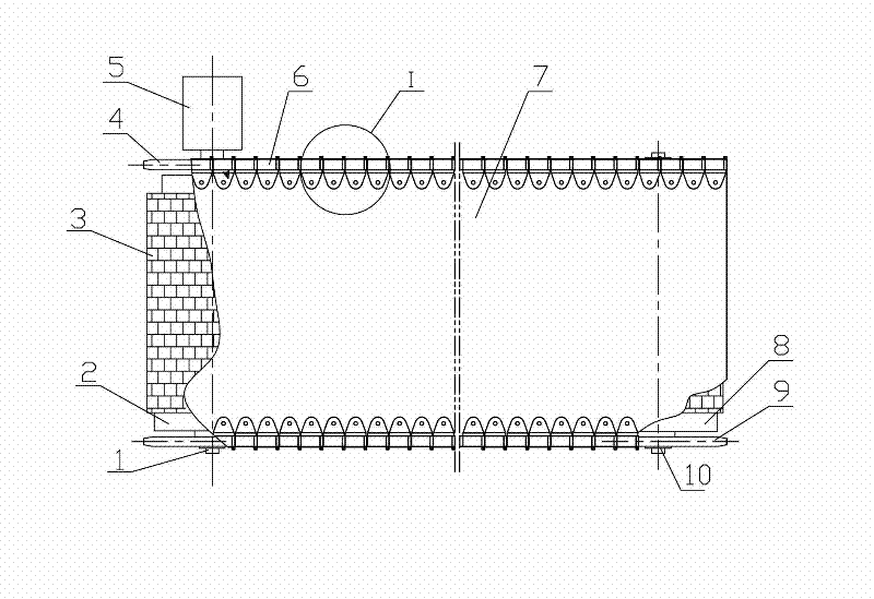
[0016] Such as figure 1 Shown, the belt conveyor of chain drive of the present invention, the belt conveyor of chain drive of the present invention comprises frame, is located at the driving device 5 of this frame head, the driving device that is connected with this driving device 5 Shaft 1, the drive roller 2 arranged in the middle of the drive shaft 1, the rotary shaft 10 arranged at the tail of the frame, the rotary roller 8 arranged in the middle of the rotary shaft 10, the rotary roller 8 and the described A group of belt idlers and conveyor belts 7 between the drive rollers 2 are characterized in that the two ends of the drive shaft 1 are respectively connected with the drive sprocket 4, and the two ends of the rotary shaft 10 are respectively connected with the rotary chain The wheel 9 is connected, the rotary sprocket 9 and the dr...


PUM


Abstract

The invention belongs to the technical field of belt conveyers, and particularly relates to a chain-transmission belt conveyer, which comprises a machine frame, a driving device, a driving shaft, a driving roller, a rotating shaft, a rotating roller, a group of belt carrier rollers and a conveying belt, wherein two ends of the driving shaft are connected with driving chain wheels respectively; two ends of the rotating shaft are connected with rotating chain wheels respectively; the rotating chain wheels and the driving chain wheels are both in meshed connection with an annularly-closed chain; the lateral edge of the conveying belt is connected with the chain; anti-skidding rubber layers are arranged on outer surfaces of the driving roller and the rotating roller; the chain consists of chain links which are connected mutually, and each chain link consists of a dual-lug chain plate, a chain sleeve, a chain shaft, a flat chain plate, a limit pin shaft and a fastening assembly; and a group of bosses are distributed on the anti-skidding rubber layers uniformly. The invention has the advantages that: the conveying belt does not have the phenomena of slipping, off-slipping, material accumulation and the like, and the chain-transmission belt conveyer is simple in a structure, low in transformation cost and convenient to install and is suitable to be popularized in mine enterprises energetically.

Description

technical field [0001] The invention belongs to the technical field of belt conveyors, in particular to a chain-driven belt conveyor. Background technique [0002] At present, in the mining industry, ore and material transportation are mainly carried out by belt conveyors. This kind of belt conveyor generally includes a driving mechanism, a driving roller (head wheel), a supporting wheel, a rotary wheel (tail wheel), a conveyor belt, etc. ) and the conveyor belt to transmit power, due to the deflection of the feeding point for the belt conveyor, the eccentric impact of the bottom mineral material on the conveyor belt, the deviation of the installation angle of the head and tail wheels, etc., the belt conveyor The conveying belt frequently deviates and misplaces, causing the material to be spilled during the transportation process. Even if a nuclear detector is installed in a few parts, because the conveying belt deviates seriously, the error of the detection result is also ...

Claims


Application Information

Patent Timeline
Patent Type & Authority Applications(China)
IPC IPC(8): B65G23/14B65G23/04B65G39/02
Inventor 李宇
Owner ANSTEEL GRP MINING CO LTD
Why Eureka
Try Eureka