Optical mixer of free space

An optical mixer and free space technology, applied in the coupling of optical waveguide, optics, instruments, etc., can solve the problems of mechanical shock and vibration instability, inflexible cost, bulky optical fiber equipment, etc., and achieve good stability and structure compact effect

Active Publication Date: 2011-10-19
O NET COMM (SHENZHEN) LTD
View PDF4 Cites 19 Cited by
  • Summary
  • Abstract
  • Description
  • Claims
  • Application Information

AI Technical Summary

Problems solved by technology

Furthermore, fiber-based devices are inherently bulky and unstable to mechanical shock and vibration; while waveguide-based products suffer from problems from high insertion loss, high polarization dependence, and manufacturing yield
Waveguide-based products are inflexible and expensive

Method used


Image

  • Optical mixer of free space
  • Optical mixer of free space
  • Optical mixer of free space

Examples


Embodiment Construction

[0021] The working principle of the free-space optical mixer of the present invention will be further described below in conjunction with the accompanying drawings.

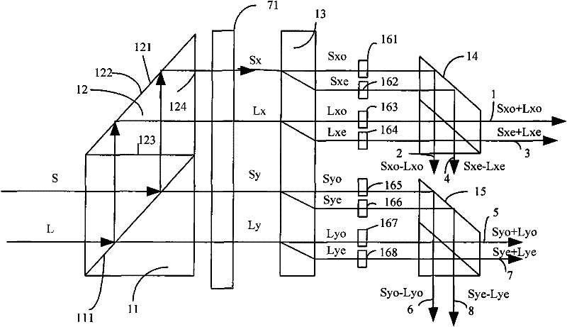
[0022] like figure 1 Shown: the light mixer 10 includes a polarization beam splitter 11, a triangular prism 12, a birefringent crystal 13, a first light combiner 14, and a second light combiner 15, and the bottom of the polarization beam splitter 11 is provided with Triangular prism 12, the inside of the hypotenuse 121 of the triangular prism 12 is coated with a reflective film 122, and the two right-angled sides 123, 124 are coated with an anti-reflection coating, wherein the triangular prism 12 and the polarizing beam splitter 11 are integrated, and the A birefringent crystal 13 and light combiners 14 and 15 are sequentially arranged on the right hand side of the polarization beam splitter.

[0023] Wherein, a first phase adjuster 161, a second phase adjuster 162, a third phase adjuster 163, a second phase adj...


PUM


Abstract

The invention provides an optical mixer of free space. The optical mixer is characterized in that: a polarizing splitter respectively separates beam S and beam L into horizontal polarization beams Sx and Lx as well as vertical polarization beams Sy and Ly; at least one birefringence crystal divides the horizontal polarization beams Sx and Lx as well as the vertical polarization beams Sy and Ly into beams Sxo, Sxe, Lxo, Lxe, Syo, Sye, Lyo, and Lye; and then beam Sxo+Lxo, beam Sxo-Lxo, beam Sxe+jLxe, beam Sxe-jLxe, beam Syo+Lyo, beam Syo-Lyo, beam Sye+jLye, beam Sye-jLye are combined by a light combiner and are output by a port. The advantages of the invention are as follows: an optical mixer of free space is allowed by utilizing a birefringence crystal, so that beams with different polarization can be separated well in free space; and the optical mixer has a compact structure and good stability.

Description

technical field [0001] The invention relates to a coherent detection device, in particular to an optical mixer with compact structure, high splitting ratio and better stability. Background technique [0002] The optical coherent receiver requires that the polarization state of the signal is the same as that of the reference beam, and the prior art optical mixer cannot flexibly control the polarization state, so an additional interference controller is added to ensure the polarization state. [0003] Prior art optical hybrids typically use two 50 / 50-beam splitters and two beam combiners, plus a 90-degree phase switcher. These optical hybrids are used to realize all-fiber or planar waveguide technologies, but both approaches have their own drawbacks. Both techniques require sophisticated temperature control circuitry to maintain a precise optical path length difference to maintain an accurate phase of the output light. Furthermore, fiber-based devices are inherently bulky an...

Claims


Application Information

Patent Timeline
Patent Type & Authority Applications(China)
IPC IPC(8): G02B6/26G02B27/12
CPCG02B27/283
Inventor 陈彬任晓晖陈林永谢红
Owner O NET COMM (SHENZHEN) LTD
Why Eureka
Try Eureka