Voltage converter

A technology of voltage converters and capacitors, which is applied in the direction of output power conversion devices, electrical components, and conversion equipment without intermediate conversion to AC, which can solve problems such as failure, high-frequency interference, and performance loss.

Active Publication Date: 2011-10-19
NXP BV
View PDF3 Cites 4 Cited by
  • Summary
  • Abstract
  • Description
  • Claims
  • Application Information

AI Technical Summary

Problems solved by technology

[0011] - Interference will self-contaminate the chip using this DC/DC converter, causing loss of performance or even beco

Method used


Image

  • Voltage converter
  • Voltage converter
  • Voltage converter

Examples


Embodiment Construction

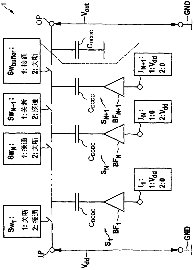
[0033] figure 1 A programmable charge pump is shown, to which the invention can be applied. The following description is based on a boost converter. However, the same principles apply to buck converters. In a buck converter, charge sharing between stages is used.

[0034] Programmable charge pump 1 has a series of stages S 1 ... S N , S N+1 , each stage contains: a capacitor C as a charge storage element DCDC ; as a switch Sw 1 ...Sw N ,Sw N+1 MOSFET; and a backplane driver as a switching device (not shown). As shown, each corresponding charge pump also includes a buffer BF 1 ...BF N , BF N+1 , buffer BF 1 ...BF N , BF N+1 with input I 1 ...I N , I N+1 , to receive the clock input signal and the voltage Vdd.

[0035] A voltage source between the input terminal IP and the ground terminal GND generates an input voltage Vdd, and this input voltage Vdd is supplied to the charge pump device 1 . The stages are connected one after the other in a cascaded fashion. ...


PUM


Abstract

A voltage converter comprises at least two capacitive charge pump stages, each comprising a capacitor, a charging switch through which a capacitor charging current is adapted to flow, and a control circuit for controlling the charging switch. wherein the control circuit for at least one charge pump stage comprises current limiting means for limiting the current through the charging switch. By limiting the current flowing through the switch, current spikes are avoided, which reduces high frequency distortion.

Description

technical field [0001] The invention relates to a voltage converter for converting an input voltage into an output voltage. Background technique [0002] In current IC technology, there is an urgent need to improve the efficiency of the power system to get the maximum operating time from one or more batteries. [0003] The voltage produced by the battery is often not at the desired level, so voltage-to-voltage conversion is required. In order to minimize losses, DC / DC converters are used to perform this conversion (boost or buck conversion) in most cases. Coils or capacitor banks can be used. [0004] In particular, the present invention relates to DC / DC converters using capacitors as switching mechanisms. [0005] A capacitive boost converter operates using a charge pump. A voltage converter may have several charge pump stages arranged in cascade. When the switches drive the drivers of the first stage, the charge storage elements of the first stage are charged. In thi...

Claims


Application Information

Patent Timeline
IPC IPC(8): H02M3/07
CPCH02M1/44H02M3/073H02M1/0029
Inventor 布拉姆·范斯特罗腾
Owner NXP BV
Why Eureka
Try Eureka