
Driving control method of low-loss hybrid stepping motor

A stepping motor, hybrid technology, applied in the direction of motor generator control, control system, electrical components, etc., can solve the problems of increasing power tube switching loss, increasing motor core loss, core heating, etc., to reduce drive Effects of system loss, reduction of hardware cost, and improvement of system efficiency

Inactive Publication Date: 2011-11-30
FUZHOU UNIV
View PDF0 Cites 0 Cited by
  • Summary
  • Abstract
  • Description
  • Claims
  • Application Information

AI Technical Summary

Problems solved by technology

No matter the load is light or heavy, the current amplitude is always controlled at the rated peak level of the motor, so that when the motor is lightly loaded, a large reactive current flows in the winding, resulting in three disadvantages: 1) a large reactive current in the stator winding resistance 2) The large reactive current produces a large armature reaction, which makes the air gap magnetic field sharply saturated, the motor core loss increases significantly, and the core heats up seriously; 3) Very large The reactive current of the driver flows through the power tube of the driver, which increases the switching loss of the power tube
However, this control strategy requires coaxial installation of a sensor for detecting the rotor position, which increases the cost of the stepper motor drive control system; at the same time, the connecting wires between the position sensor and the drive control hardware also reduce the reliability of the drive system
Moreover, the vector directional control algorithm is complex and requires more resources of the CPU

Method used


Image

  • Driving control method of low-loss hybrid stepping motor
  • Driving control method of low-loss hybrid stepping motor
  • Driving control method of low-loss hybrid stepping motor

Examples


Embodiment Construction

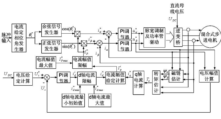
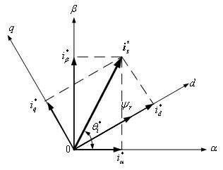
[0033] like figure 1 and figure 2 as shown, figure 1 is a system control principle block diagram of the present invention, figure 2 is the definition of coordinates and related vectors, and the winding current of the hybrid stepper motor can be decomposed into d-axis components in the rotor synchronous dq rotating coordinate system and the q-axis component ,in It is used to generate electromagnetic torque and drive external machinery, which belongs to active current; It is used to adjust the air gap flux linkage, which belongs to reactive current. Will By controlling to the lowest value, the winding current amplitude can be reduced to the minimum value, thereby reducing the winding copper loss, core iron loss and power tube switching loss to the minimum. Please continue to refer to figure 1 ,Depend on figure 1 It can be seen that the input pulse is sent to the current given phase angle generator to obtain the current given phase angle ; Simultaneously send co...


PUM


Abstract

The present invention relates to driving control method and circuit of a low-loss hybrid stepping motor. The control method comprises the following steps of: directly estimating electromagnetic torque in a stator coordinate system and calculating a q-axis active current component; and outputting a d-axis reactive current component in a closed ring by utilizing a winding voltage; and calculating a given current amplitude according to the active current component and the reactive current component to form the micro-step control of the hybrid stepping motor with variable current amplitude. The control method is suitable for two-phase or multi-phase hybrid stepping motors and can effectively prevent a driving control system from heating and prolong the service life of the motor.

Description

technical field [0001] The invention relates to a low-loss hybrid stepping motor drive control method and circuit. Background technique [0002] The rotor of the hybrid stepping motor is excited by permanent magnets. The motor has the advantages of large output torque and high efficiency when it is working. It is widely used in CNC machine tools, engraving machines, embroidery machines, medical equipment and other occasions that require precise position control. At present, hybrid stepper motors mostly use micro-step control methods to reduce the rotor rotation step angle and improve the rotation stability of the rotor at low speed and low subdivision. The micro-step control adopts the winding current closed-loop structure, the current amplitude is constant, and the phase is increased by micro-steps controlled by external pulses, so that a series of current vectors with constant amplitude and discrete phases are generated in the stator air gap to drive the rotor to rotate in...

Claims


Application Information

Patent Timeline
Patent Type & Authority Patents(China)
IPC IPC(8): H02P8/16
Inventor 周扬忠
Owner FUZHOU UNIV
Learn More