Switch and capacitor integrated quick discharge unit

A discharge unit and capacitor technology, applied in the field of fast discharge, can solve the problem of increasing branch inductance, etc., to achieve the effect of increasing output current, reducing module size and branch inductance, and reducing rise time

Inactive Publication Date: 2011-10-19
NORTHWEST INST OF NUCLEAR TECH
View PDF3 Cites 24 Cited by
  • Summary
  • Abstract
  • Description
  • Claims
  • Application Information

AI Technical Summary

Problems solved by technology

However, the capacitors and switches in the current branch are separated, refer to figure 1 As shown: including gas switch 21, upper capacitor 22, and lower capacitor 23, con...

Method used


Image

  • Switch and capacitor integrated quick discharge unit
  • Switch and capacitor integrated quick discharge unit
  • Switch and capacitor integrated quick discharge unit

Examples


Embodiment Construction

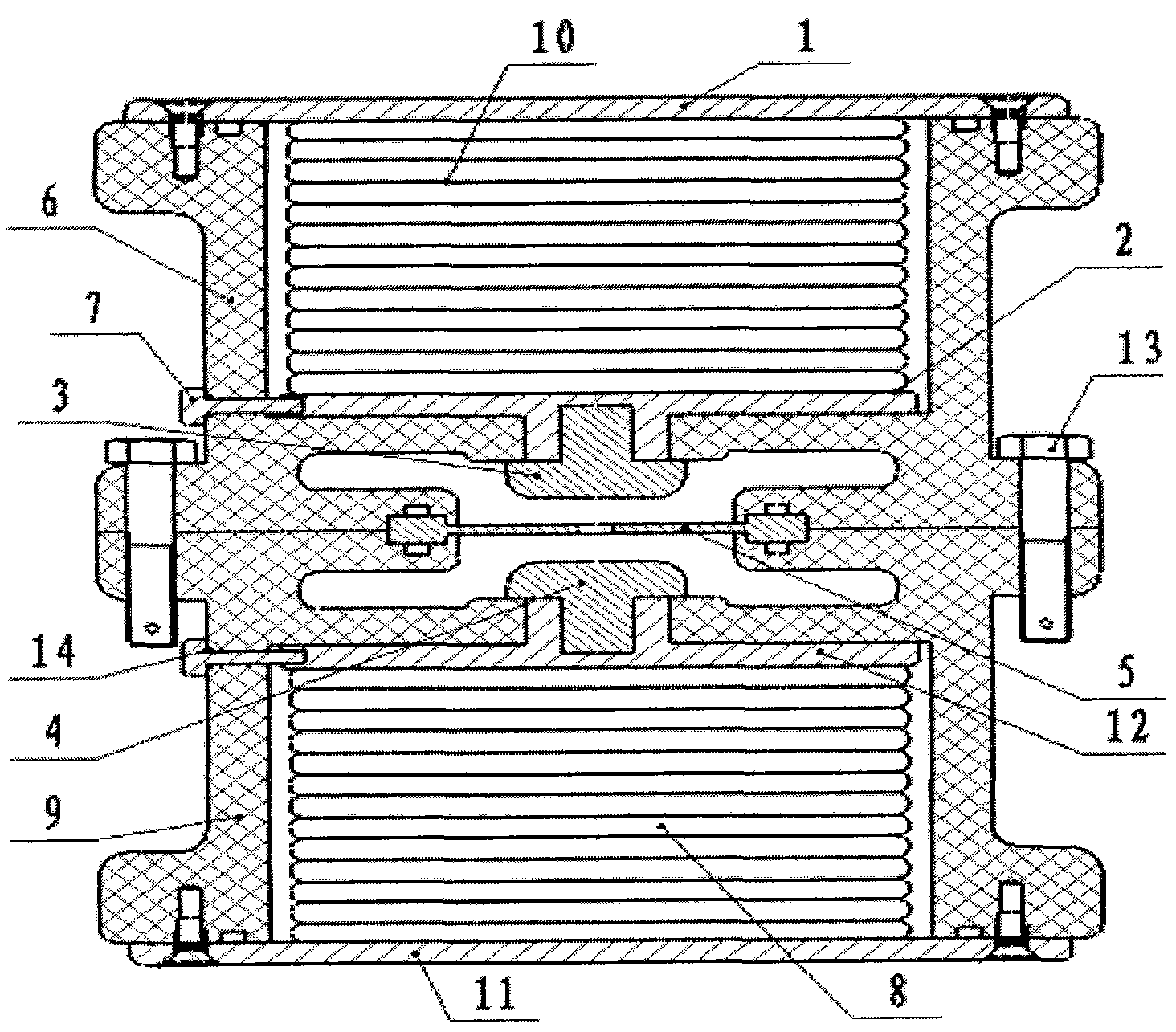
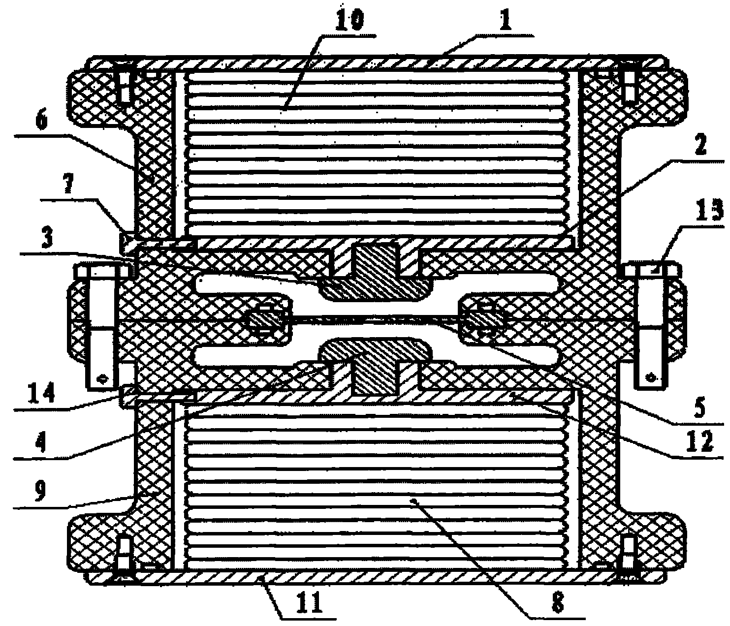
[0018] combine figure 2 Describe the implementation technical scheme of the capacitor and switch integrated single-stage discharge unit, the double-terminal lead-out electrode insert of the capacitor element (10) connected in series, the high-voltage electrode 2 of the upper capacitor, the low-voltage lead-out electrode 1 of the upper capacitor, the insulating shell 6, and the charging lead-in electrode 7 forms a capacitor, the capacitor element 8 is connected in series with the double-terminal lead-out electrode insert, the lower capacitor low-voltage lead-out electrode 11, the lower capacitor high-voltage electrode 12, the insulating case 9, and the charging lead-in electrode 14 forms another capacitor, the capacitor insulating case 6 The lower end face and the upper end face of the capacitor insulating shell 9 form a gas switch sealed chamber through insulating fastening screws 13. The upper and lower high-voltage electrodes 3, 4 of the gas switch and the trigger electrode ...


PUM


Abstract

The invention discloses a switch and capacitor integrated quick discharge unit. Two capacitors and a switch arranged between the two capacitors form a coaxial structure; a high-voltage electrode (2; 12) is led from a capacitor and is simultaneously used as the high-voltage electrode of a gas switch; and the capacitors and the switch commonly share one insulating shell. By adopting the discharge unit, under the same energy storage condition, the module dimension and the branch inductance can be reduced obviously; the output current can be improved; the boosting time can be reduced; the discharge current peak can be improved, the pulse current front can be shortened, and the switch and capacitor integrated quick discharge unit has wide application in pulse power primary energy storage Marx generators and linear pulse transformer driving sources.

Description

technical field [0001] The invention relates to a fast discharge technology integrating a switch and a capacitor, in particular to a fast discharge unit integrating a switch and a capacitor. It is widely used in pulse power primary energy storage Marx generators and linear pulse transformer drive sources. Background technique [0002] Pulse power technology has extremely important applications in national defense and civilian fields such as nuclear weapon physics, high energy density physics, radiation effect simulation, inertial confinement fusion (ICF) and fusion energy (IFE), and the pulse power drive source is the basis and premise of the application. At present, the world is actively studying the construction of the next generation of large-scale pulse power sources based on the linear pulse transformer (LTD). The most basic unit "branch" in LTD consists of two capacitors with a working voltage of 100kV and a capacity of tens of nF connected in series with a gas switch...

Claims


Application Information

Patent Timeline
IPC IPC(8): H02M9/04
Inventor 孙凤举邱爱慈盖同阳梁天学曾江涛丛培天尹佳辉
Owner NORTHWEST INST OF NUCLEAR TECH
Why Eureka
Try Eureka