Cutting insert

A cutting tool and cutting edge technology, applied to cutting blades, tools for lathes, milling cutters, etc., can solve the problems of reduced service life of the cutting tool 20, reduced cutting quality, and easy damage of the cutting tool 20, and achieve smooth cutting Process, the effect of effective heat dissipation

Inactive Publication Date: 2011-10-19
TAEGUTEC
View PDF8 Cites 0 Cited by
  • Summary
  • Abstract
  • Description
  • Claims
  • Application Information

AI Technical Summary

Problems solved by technology

[0006] The cutting tool 20 may be easily damaged due to the heat retained within the cutting tool, thus resulting in a reduced service life of the cutting tool 20 and a reduction in cutting quality

Method used


Image

  • Cutting insert
  • Cutting insert
  • Cutting insert

Examples


Embodiment Construction

[0027] Hereinafter, a cutting tool according to a preferred embodiment of the present invention will be described in detail with reference to the accompanying drawings.

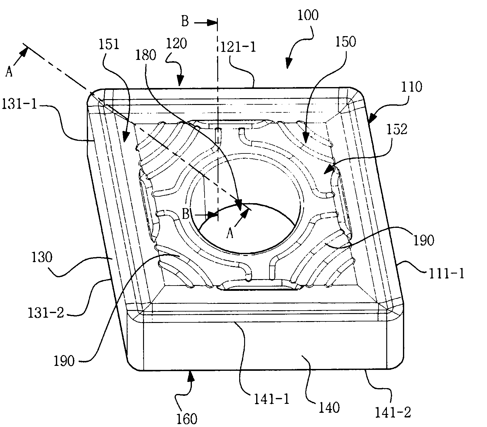
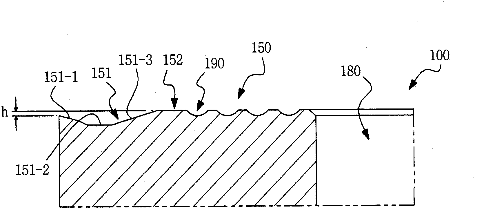
[0028] figure 2 is a perspective view of a cutting tool according to a first embodiment of the present invention, image 3 is along figure 2 The cross-section drawn by the line A-A and Figure 4 is along figure 2 Sectional drawing made by line B-B. To simplify the drawings, in image 3 and Figure 4 Only the top surface of the tool is shown in .

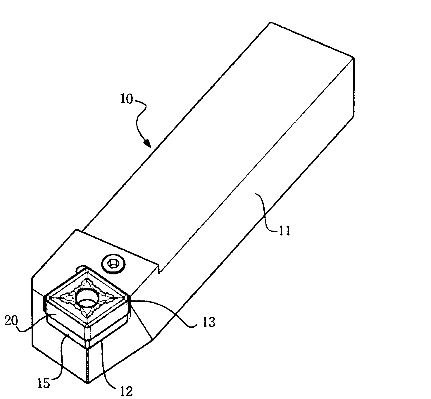
[0029] The cutting tool 100 according to the first embodiment of the present invention has a top surface 150 and a bottom surface 160 facing each other, four (4) side surfaces 110 , 120 , 130 and 140 connecting the top surface 150 and the bottom surface 160 . Here, the through hole 180 passes through the central portion of each of the top surface 150 and the bottom surface 160 and serves as a clamping hole when the cutting tool 100 is mounted to the tool h...


PUM


Abstract

The present invention discloses a cutting insert being capable of radiating effectively heat generated during the cutting machining process and having a structure by which a sufficient surface area is in contact with a tool holder and cutting fluid can be smoothly flowed. The cutting insert according to the present invention comprises an upper face and a lower face being opposite to each other, a plurality of side faces connecting the upper face and the lower face and a through hole passing through the upper face and the lower face, the upper face being divided into a periphery region disposed adjacently to cutting edges formed by the upper face and the side faces, and a central protruded region disposed between the through hole and the periphery region and surrounding the through hole, the central protruded region being placed higher than the edges. Here, the periphery region is formed along all the cutting edges and comprising an descent face inclined downward from the cutting edge to the central protruded region, a bottom face and an ascent face inclined upward from the bottom face to the central protruded region, and a plurality of grooves are formed on the central protruded region of the upper face, the groove being formed such that both ends of respective groove are directed to the adjacent cutting edges.

Description

technical field [0001] The present invention relates to a cutting tool, and more particularly, the invention relates to a cutting tool having a structure for efficiently dissipating cutting heat generated during a cutting process and enabling a smooth flow of cutting fluid. Background technique [0002] In general, heat generated from workpieces made of stainless steel or Inconel during turning operations such as outside diameter turning processes, surface turning processes, and drilling processes is not easily transferred to chips and retained in the cutting tool. Therefore, there is a problem that the remaining heat greatly reduces the service life of the cutting tool. [0003] figure 1 is a perspective view of a conventional tool holder for a cutting machining process, a tool holder 10 for cutting machining includes a carbide plate 15, a cavity 12, a cavity 13 and a shank portion 11, and a cutting tool 20 is installed into the cavity 12 and the cavity 13 . [0004] Dur...

Claims


Application Information

Patent Timeline
Patent Type & Authority Applications(China)
IPC IPC(8): B23B27/16B23C5/20
CPCB23B27/141B23B2200/086B23B2222/36B23B2222/80B23B2250/12Y10T82/10Y10T407/235
Inventor 朴弘植周长赫
Owner TAEGUTEC
Why Eureka
Try Eureka