Two-stage injection heat pump type heat exchange unit
A heat exchange unit and ejector technology, applied in the energy field, can solve the problems that cannot be further reduced
- Summary
- Abstract
- Description
- Claims
- Application Information
AI Technical Summary
Problems solved by technology
Method used
Image

Examples
Embodiment 1
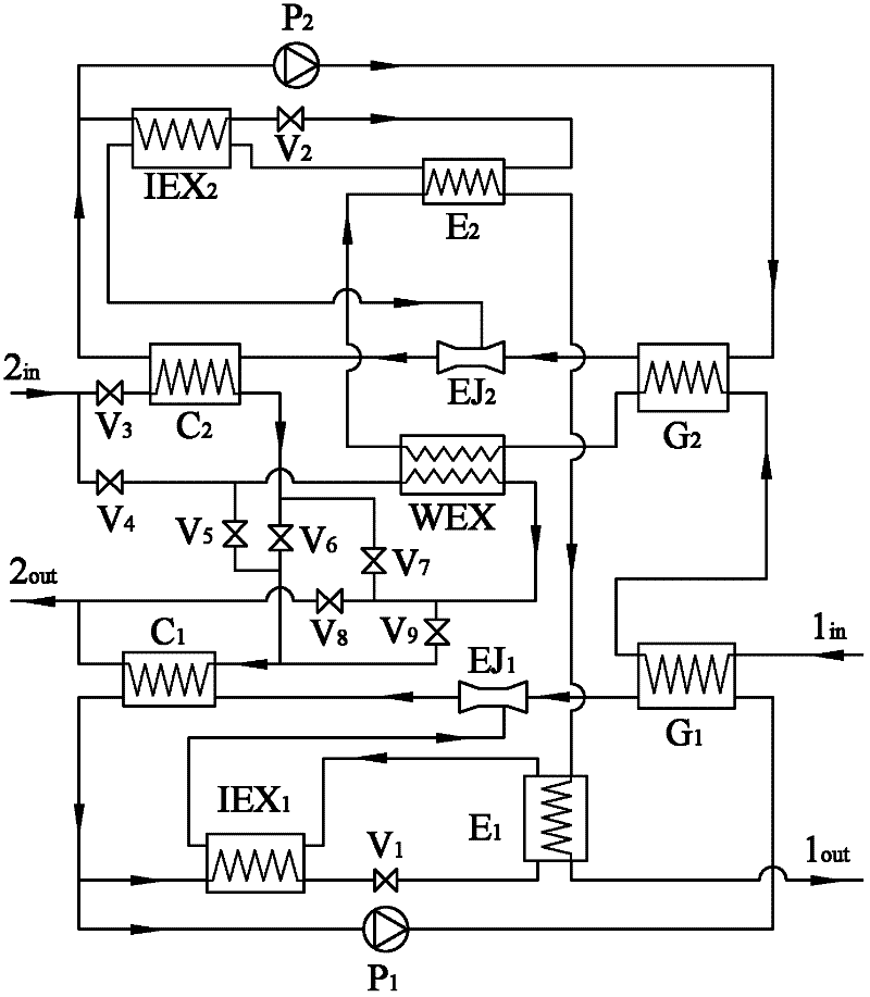
[0025] Such as figure 1 As shown, the two-stage injection heat pump heat exchange unit is composed of two-stage injection heat pumps, heat exchangers, connecting pipes, valves and other accessories. Among them, the connecting pipeline is divided into working medium pipeline system and waterway system, and the waterway system is further divided into primary side pipeline system and secondary side pipeline system. The two-stage ejector heat pump and the water-to-water heat exchanger are organically combined through connecting pipelines to form a two-stage ejector heat pump heat exchange unit. Among them, each stage of ejector heat pump is composed of generator, condenser, evaporator, ejector, regenerator, pump, connecting pipelines and valves and other accessories. The working medium circulation process of each stage of ejector heat pump: the high-pressure working medium liquid from the pump enters the generator, is heated by the hot water in the primary side pipeline, and gene...
Embodiment 2
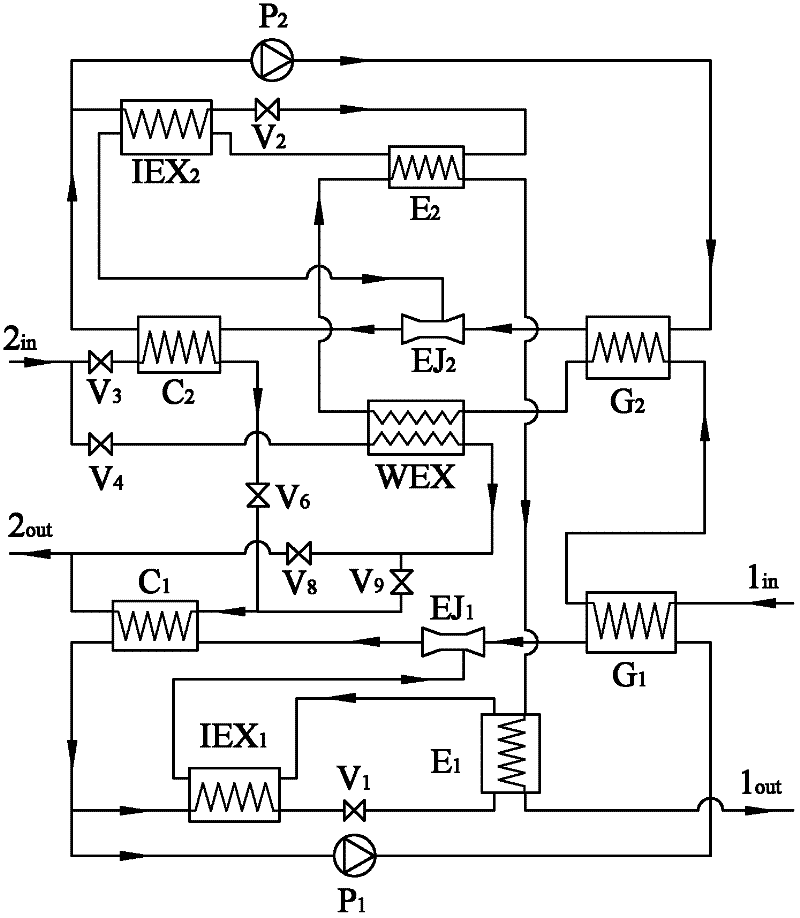
[0029] Such as figure 2 As shown, the two-stage injection heat pump heat exchange unit is composed of two-stage injection heat pump, water-to-water heat exchanger WEX, connecting pipelines, valves and other accessories. The connection mode of the ejector heat pump pipeline and the primary side pipeline is the same as that of Embodiment 1.
[0030] The secondary side pipeline is produced in a mixed or series way. When the mixed connection mode is used, the fifth valve V 5 , the seventh valve V 7 closed, the third valve V 3 , the fourth valve V 4 , the sixth valve V 6 Open, the hot water in the secondary side pipeline is divided into two ways, one way of hot water flows through the third valve V in sequence 3 , into the second-stage ejector heat pump condenser C 2 After being heated by the heat pump working fluid, it flows through the sixth valve V 6 , into the first stage ejector heat pump condenser C 1 Heated by the heat pump working fluid, another way of hot water f...
Embodiment 3
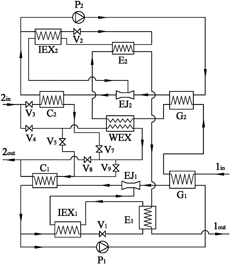
[0032] Such as image 3 As shown, the two-stage injection heat pump heat exchange unit is composed of two-stage injection heat pump, heat exchanger WEX, connecting pipelines, valves and other accessories. The connection mode of the ejector heat pump pipeline and the primary side pipeline is the same as that of Embodiment 1.
[0033] The secondary side pipelines are connected in parallel or in series. When parallel connection is used, the sixth valve V 6 closed, the third valve V 3 , the fourth valve V 4 , the fifth valve V 5 , the seventh valve V 7 Open, the hot water in the secondary network is divided into three ways, and the hot water in one way passes through the fourth valve V 4 After entering the water-water heat exchanger WEX is heated by the hot water from the primary side pipeline, the other hot water passes through the fourth valve V 4 , the fifth valve V 5 Enter the first stage ejector heat pump condenser C 1 Heated by the heat pump working medium steam, th...
PUM
 Abstract
Description
Claims
Application Information
 - R&D
- Intellectual Property
- Life Sciences
- Materials
- Tech Scout
- Unparalleled Data Quality
- Higher Quality Content
- 60% Fewer Hallucinations
Browse by: Latest US Patents, China's latest patents, Technical Efficacy Thesaurus, Application Domain, Technology Topic, Popular Technical Reports.
© 2025 PatSnap. All rights reserved.Legal|Privacy policy|Modern Slavery Act Transparency Statement|Sitemap|About US| Contact US: help@patsnap.com