Conical tri-rotor continuous mixing unit with rotors in linear arrangement

A conical three-rotor, in-line technology, used in mixers, mixers, dissolving and other directions with rotating stirring devices, can solve the problems of low efficiency and difficult to achieve the same mixing quality, and achieve higher output and higher mixing. The effect of refining and enhancing the effect of axial conveying

Inactive Publication Date: 2011-11-02
BEIJING UNIV OF CHEM TECH
View PDF5 Cites 3 Cited by
  • Summary
  • Abstract
  • Description
  • Claims
  • Application Information

AI Technical Summary

Problems solved by technology

Open mixer and internal mixer are batch mixing equipment, not only low in efficiency,

Method used


Image

  • Conical tri-rotor continuous mixing unit with rotors in linear arrangement
  • Conical tri-rotor continuous mixing unit with rotors in linear arrangement
  • Conical tri-rotor continuous mixing unit with rotors in linear arrangement

Examples


Embodiment Construction

[0020] specific implementation plan

[0021] This implementation case is a two-stage conical three-rotor continuous mixing unit.

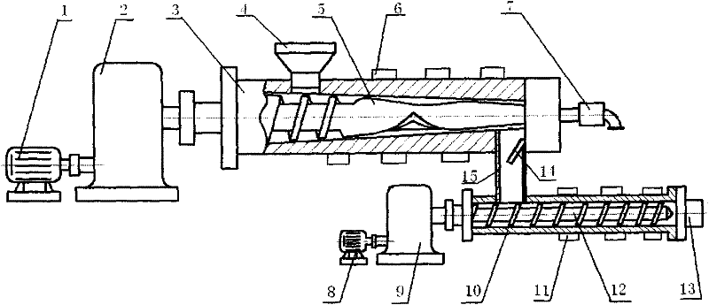
[0022] The conical three-rotor continuous mixing unit with conical rotors arranged in a straight line can be composed of a conical three-rotor continuous mixer connected with a screw extruder, see figure 1 . The mixing part mainly includes: motor 1, deceleration and distribution box 2, barrel 3, feeding device 4, heating device 5, conical rotor 6, and rotor cooling device 7. The screw extrusion part includes: a motor 8, a reduction box 9, a barrel 10, a heating device 11, a screw 12, and a nose die 13. The mixing part and the screw extruding part are connected by a cylinder 15, in which a discharge valve 14 with an adjustable opening is provided. Motor 1, deceleration and distribution box 2 form the transmission device of the equipment.

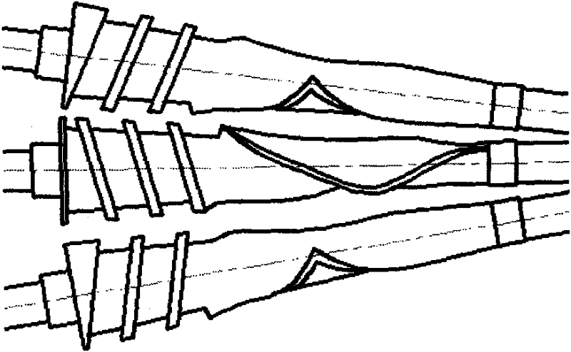
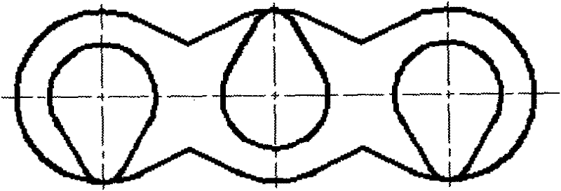
[0023] The mixing part uses three conical rotors, and when installed, their centerlines are located in the ...


PUM


Abstract

The invention provides a conical tri-rotor continuous mixing unit with rotors in linear arrangement, mainly comprising a mixing part and an exhausting part and a single-order or dual-order mode is adopted in the unit. The mixing part mainly comprises a charging device, a cylinder, conical rotors, a heating and cooling device and a driving device; the central lines of the three conical rotors for mixing are in the same plane and form fixed cone angles in linear arrangement in installation; the outer diameter outlines of the three rotors are tapered and each motor is provided with a charging segment and a mixing segment; the charging segment is of a spiral conveyance structure; and for a conical surface vertical to the outer outlines of the rotors, the mixing segment is of a cam shape, S shape or quadrangular rotor shape and the like. When the single-order mode is adopted, a spiral structure is adopted at the tail ends of the rotors so as to form a pressure to transmit materials to a machine head; and when the dual-order mode is adopted, mixing materials enter into the next-order screw extruder by a valve to form a pressure to transmit the materials to the machine head. For the two modes, the machine head suitable for a cavity is utilized to carry out pelleting or molding, and for the purpose of intensifying the pressure, a melt pump can be connected with the machine head. The three rotors can rotate at the same speed or different speeds, and when the three motors rotate, multiple shearing areas, stretching areas and kneading areas are formed, thus the materials among the rotors are exchanged frequently, thereby improving the plasticating performance, the melting performance and the dispersion performance effectively, shortening the processing time and improving the yield. The mixing unit is used for mixing, pelleting and other processes in processing rubbers, coatings, propellants, explosives, paper pulps, plastics, foods, pharmacy, feeds and the like.

Description

technical field [0001] The invention relates to a conical three-rotor continuous mixing unit with rotors arranged in a straight line, which can be used for mixing and granulation processes in the processing of rubber, paint, propellant, explosives, paper pulp, plastics, food, pharmaceuticals, feed, etc. Background technique [0002] Mixing is a key process link that determines the performance of polymer products, especially for high viscoelastic materials such as rubber. The uniformity and stability of material mixing is the key to ensure the quality of polymer products. The realization of uniform mixing mainly depends on mixing technical equipment, including open mixer, internal mixer, double-rotor continuous mixer and screw extruder. Industrially, screw extruders are mainly used for plasticizing plastics, food and thermoplastic elastomers, while the other three are mainly used for mixing complex materials such as rubber, coatings, explosives and propellants. Open mills a...

Claims


Application Information

Patent Timeline
IPC IPC(8): B01F7/02B29B7/46
CPCB29B7/465B29B7/485B29B7/487B29B7/489B29B7/582B29B7/60B29B7/7485B29B7/7495B29B7/826B29C48/285B29C48/365B29C48/39
Inventor 王克俭
Owner BEIJING UNIV OF CHEM TECH
Why Eureka
Try Eureka