Circulating feeding system for producing ceramic wall and flow tiles

A technology for circulating cloth, wall and floor tiles, applied in the direction of forming conveyors, etc., can solve the problems of affecting the quality of cloth, complex design structure, high manufacturing cost, and achieve the effect of enriching patterns and improving production efficiency.

Inactive Publication Date: 2011-11-02
FOSHAN DONGCHENGHUI TECH HLDG
View PDF5 Cites 6 Cited by
  • Summary
  • Abstract
  • Description
  • Claims
  • Application Information

AI Technical Summary

Problems solved by technology

Now there are at least one stacking, sprinkling, filling and other work steps in a single process, so the existing equipment will often affect the efficiency of production due to the mismatch between the various links. Chinese patent CN2678854Y discloses A "belt-type ceramic press multi-distribution device" is proposed, and its technical solution is "comprising a press mold, a transmission belt, a billet rolling table, a driving roller and a driven roller, and its characteristic is that the transmission belt is set There are multiple filling chambers and brick pushing chambers, and a material distributing mechanism is arranged above the filling chamber. The above-mentioned technical solution solves the problem of interfacing the powder from distributing to pressing through the plane conveyor belt with intermittent reciprocating motion. But this technical solution also has the following deficiencies: a. Since the packing chamber cavity and the brick pushing chamber cavity are all arranged on the transmission belt, the design structure is relatively complicated, and the quality of the cloth will not only be affected by the large transmission vibration during the entire working process , will also reduce the working efficiency of the whole machine, b. Since the entire conveying face traverses the press and needs to reciprocate periodically, its structure is relatively complicated, and the manufacturing cost of the whole machine is relatively high

Method used


Image

  • Circulating feeding system for producing ceramic wall and flow tiles
  • Circulating feeding system for producing ceramic wall and flow tiles

Examples


Embodiment Construction

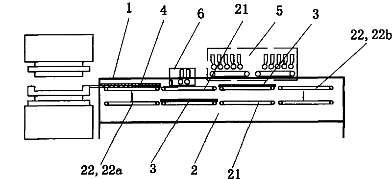
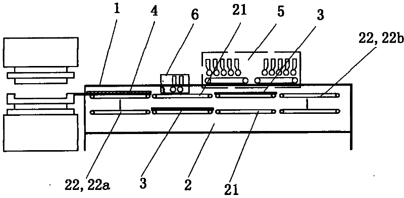
[0010] The present invention as figure 1 As shown, a circulating distribution system for producing ceramic wall and floor tiles includes a frame 1, a conveying device 2, a pallet 3, a feeding device 4, a distributing station device 5, and a replenishing scraping device 6. The above-mentioned conveying device 2 includes a The horizontal conveying platform 21 arranged in upper and lower layers is respectively provided with a liftable vertical conveying platform 22 at the front and rear ends of the horizontal conveying platform 21, and the horizontal conveying platform 21 and the vertical conveying platform 22 together constitute a closed-loop conveying device.

[0011] The above-mentioned horizontal conveying platform 21 arranged in upper and lower layers is respectively composed of several adjacent conveying mechanisms, each conveying mechanism is provided with an independent driving device, and the conveying mechanisms are synchronous or asynchronous conveying. Each section of...


PUM


Abstract

The invention discloses a circulating cloth system for producing ceramic wall and flow tiles. The system comprises a rack, a delivery device, a supporting plate, a feeding device, a feeding station device and a supplementary material striking device; the delivery device comprises a horizontal delivery platform with an upper layer and a lower layer; the front end and rear end of the horizontal delivery platform are respectively provided with a liftable vertical delivery platform; and the horizontal delivery platform and the vertical delivery platforms form an enclosed circulating delivery device. Because a delivery system which is formed by the horizontal delivery platform and the vertical delivery platforms and the feeding device which is arranged above a front vertical lifting platform close to one end of a press are organically combined, and the synchronization implementation of multiple working procedures of feeding is realized, not only can the production efficiency be improved, but also the produced wall and floor tiles have abundant pattern effects.

Description

technical field [0001] The invention relates to a production equipment for producing ceramic wall and floor tiles, in particular to a circulation distribution system for producing ceramic wall and floor tiles. Background technique [0002] In the production of traditional ceramic wall and floor tiles, most of the equipment used is composed of two parts, namely, the powder feeding device and the powder pressing device. The latter is usually realized by a press equipped with a mold, while the former is It consists of two links: powder conveying and distributing. With the improvement of the surface pattern and color requirements of wall and floor tiles, the distributing process often develops from the original one-time distributing to multiple distributing. Now there are at least one stacking, sprinkling, filling and other work steps in a single process, so the existing equipment will often affect the efficiency of production due to the mismatch between the various links. Chine...

Claims


Application Information

Patent Timeline
Patent Type & Authority Applications(China)
IPC IPC(8): B28B5/02
Inventor 杨晓东
Owner FOSHAN DONGCHENGHUI TECH HLDG
Why Eureka
Try Eureka