Three-dimensional grid precision compensation method for industrial robot

An industrial robot and three-dimensional technology, applied in the direction of instruments, optical devices, measuring devices, etc., can solve the problems of unsatisfactory robot positioning accuracy, heavy measurement workload, and unsatisfactory results, so as to achieve simple and rapid calculation process and reduce work The effect of improving the absolute positioning accuracy

Active Publication Date: 2011-11-02
NANJING UNIV OF AERONAUTICS & ASTRONAUTICS +1
View PDF4 Cites 44 Cited by
  • Summary
  • Abstract
  • Description
  • Claims
  • Application Information

AI Technical Summary

Problems solved by technology

[0005] 1) In order to enable the trained network to achieve a certain accuracy and adapt to all points within the envelope of the robot, training the neural network requires a large number of learning samples, so the measurement workload is heavy;
[0006] 2) This method needs to convert Cartesian coordinates into joint coordinates, so it needs to find the inverse solution to the robot kinematics equation. This process requires a lot of calculation, and the effect is not ideal near the singular point;
[0007] 3) The test results show that the positioning accuracy of the robot after calibration is still not ideal

Method used


Image

  • Three-dimensional grid precision compensation method for industrial robot
  • Three-dimensional grid precision compensation method for industrial robot
  • Three-dimensional grid precision compensation method for industrial robot

Examples


Embodiment Construction

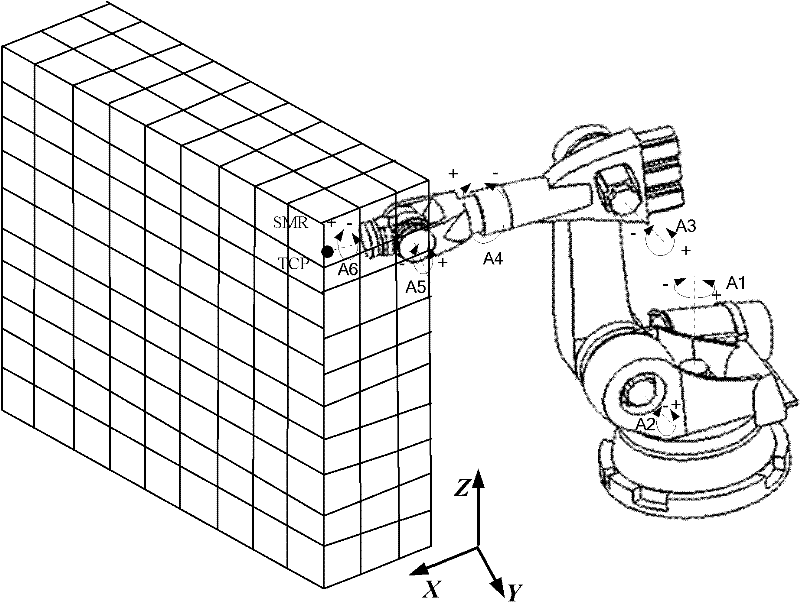
[0023] Such as figure 1 As shown, the steps of the method for compensating the accuracy of the spatial three-dimensional grid used for industrial robots in the present invention are as follows:

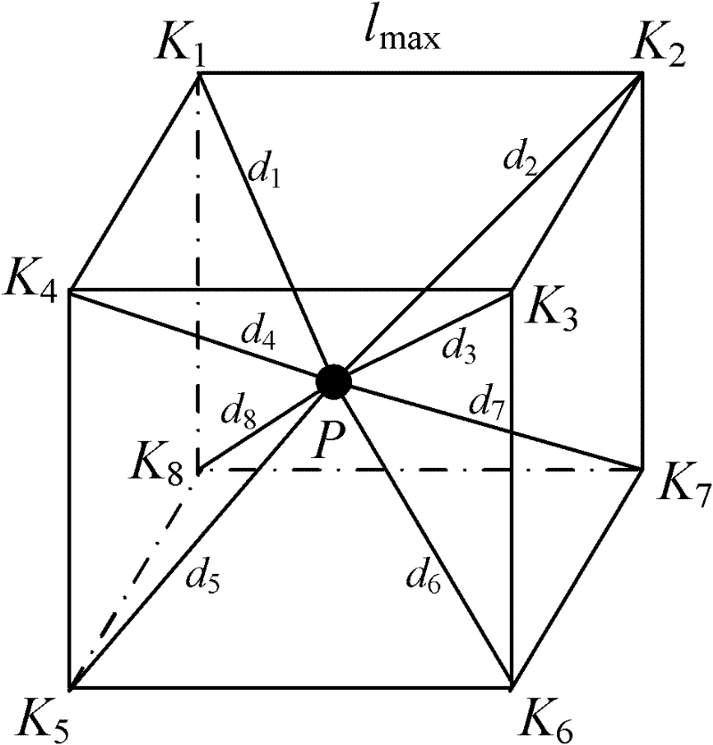
[0024] Step 1: within the range of the envelope of the industrial robot, divide the entire envelope space into a series of cubic grids in the Cartesian coordinate system according to the given maximum step size;

[0025] Step 2: Measure and establish the base coordinate system of the robot through the laser tracker, use the theoretical coordinates of the eight vertices of each cube grid divided in step 1 to control the robot for positioning, and the robot is positioned at the eight vertices of the cube grid The attitude is consistent or the deviation is within ±10°, and then the laser tracker is used to measure and record the actual positioning coordinates;

[0026] The steps to establish the association between the laser tracker and the robot base coordinate system are:

[0027] ① ...


PUM


Abstract

The invention discloses a three-dimensional grid precision compensation method for an industrial robot and belongs to the technical field of inverse calibration of industrial robots. In the method, by taking advantage of the characteristic that the industrial robot has relatively high reposition accuracy and establishing the relationship between theory coordinates and actual positioning coordinates by a laser tracker, the theoretical coordinates of any one point in a certain cubic grid divided in an enveloping space of the robot can be corrected by a spatial interpolation process, so that the absolute position precision compensation of the robot at the point is accomplished. In the method, the calculation procedure is simple and fast; the absolute position precision of the robot can be obviously improved, and the robot can be suitable for a wider application range.

Description

technical field [0001] The invention relates to a robot positioning compensation method, in particular to a spatial three-dimensional grid accuracy compensation method for industrial robots, and belongs to the technical field of industrial robot inverse calibration. Background technique [0002] The accuracy of the robot is an important index reflecting the performance of the robot, which includes absolute positioning accuracy and repeat positioning accuracy. The absolute positioning accuracy error is the deviation between the actual movement of the robot and the expected movement, which is generated by the deterministic original error (such as the error of the connecting rod parameter, the clearance of the kinematic pair, etc.); the repeat positioning accuracy error is when the robot repeatedly performs the same expected movement. The degree of mutual discreteness between the actual motions is generated by random original errors (such as joint servo positioning errors, etc....

Claims


Application Information

Patent Timeline
Patent Type & Authority Applications(China)
IPC IPC(8): G01B11/00
Inventor 田威廖文和万世明周炜沈建新李东明罗英孟华林杨汉
Owner NANJING UNIV OF AERONAUTICS & ASTRONAUTICS
Why Eureka
Try Eureka