Laser pulse synchronization control device

A laser pulse and synchronization control technology, applied in the field of optoelectronics, can solve the problem that the accuracy of the laser pulse synchronization method is difficult to further improve, and achieve the effect of improving the pulse synchronization accuracy

Inactive Publication Date: 2011-11-02
UNIV OF ELECTRONICS SCI & TECH OF CHINA
View PDF4 Cites 11 Cited by
  • Summary
  • Abstract
  • Description
  • Claims
  • Application Information

AI Technical Summary

Problems solved by technology

However, due to the uncertainty of the delay of the laser output relative to the Q-switched trigger signal, that is, the uncertainty of the laser pulse establishment time, this feedback controls the laser at the electro-optic Q-switched trigger moment of the next pulse period of each laser. The accuracy of the pulse synchronization method is difficult to further improve

Method used


Image

  • Laser pulse synchronization control device
  • Laser pulse synchronization control device
  • Laser pulse synchronization control device

Examples


Embodiment Construction

[0014] At first, illustrate the inventive thought:

[0015] Detect the time difference between two beams of light pulses in the current pulse period, and perform fast signal processing and delay time correction. One of the keys: the static optical delayer on each optical pulse provides enough time for fast signal processing and delay time correction.

[0016] Second, the present invention will be further described below in conjunction with accompanying drawing:

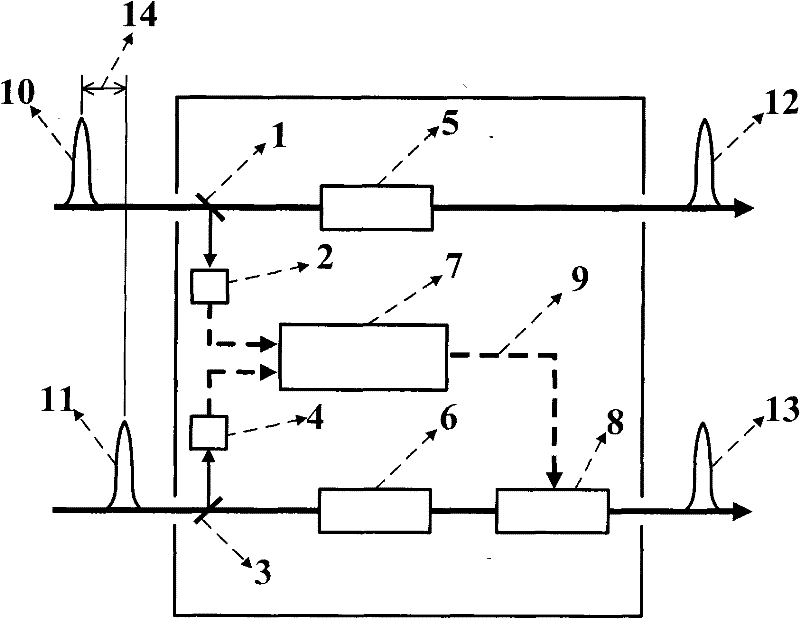
[0017] The first embodiment of the laser pulse synchronization controller that improves the synchronization accuracy provided by the present invention has a structure such as figure 1 As shown, it includes: a first beam splitter 1, a second beam splitter 3, a first photodetector 2, a second photodetector 4, a first static light delayer 5, a second static light delayer 6, a delay Time controller 7, the first dynamic light delayer 8; The first incident light pulse 10 is divided into two beams by the first beam splitte...


PUM


Abstract

The invention discloses a laser pulse synchronization control device which is connected with M paths of laser pulse sources, wherein M is a natural number larger than 1. The laser pulse synchronization control device is characterized in that: except one path, each of other paths of the laser pulse source sequentially comprises a spectroscope, a static light delayer and a dynamic light delaying module, and the one path of the laser pulse source sequentially comprises a spectroscope and a static light delayer; laser pulse sub-beams of the spectroscope of each path are input to each photo detector, and outputs of the photo detectors are connected with a delay controller; and the delay controller controls and is connected with each dynamic light delaying module. The laser pulse synchronization control device breaks through a traditional synchronization method for controlling the current electro-optical Q-switching trigger time by utilizing the feedback of previous pulse period data, and carries out fast signal processing and delay time modification by utilizing static light delay and detecting current pulse, thus pulse synchronization accuracy can be further improved, and more application requirements are met.

Description

technical field [0001] The invention relates to the field of optoelectronic technology, in particular to a laser pulse synchronization control device capable of improving synchronization accuracy. Background technique [0002] High-energy, high-peak-power lasers have important and extensive applications in the fields of laser processing, laser nonlinear effects, and remote sensing. Q-switching the laser is the main way to obtain high energy and high peak power output. In order to meet the application requirements, the methods to further increase the energy and peak power mainly include: increasing the pump injection, multi-stage cascade amplification and synchronous synthesis of multiple lasers. Due to the limitation of laser thermal effect, when the pump injection increases to a certain extent, the laser output energy and power will be saturated. Compared with cascaded amplification, multiple laser synchronous synthesis has the advantages of simple unit technology, good t...

Claims


Application Information

Patent Timeline
Patent Type & Authority Applications(China)
IPC IPC(8): H01S3/10H01S3/101
Inventor 王云祥邱琪史双瑾苏君廖云熊彩东
Owner UNIV OF ELECTRONICS SCI & TECH OF CHINA
Why Eureka
Try Eureka