Lower cantilever base for support seat of railway line contact network

A catenary and support seat technology, applied in overhead lines and other directions, can solve problems such as poor structure and strength, high replacement and maintenance costs, and affect the safety of trains, so as to achieve reasonable structure, reduce replacement and maintenance costs, and extend the effect of life

Active Publication Date: 2011-11-09
CHONGQING ZHONGCHENG PRECISION DIE FORGING
View PDF6 Cites 2 Cited by
  • Summary
  • Abstract
  • Description
  • Claims
  • Application Information

AI Technical Summary

Problems solved by technology

The lower arm base of the railway line catenary support seat of the present structure can not meet the needs of the existing railway line catenary, and mainly has the following two deficiencies: one, the lower arm base made by the existing casting process, itself The structure, strength and other properties are relatively poor, and cannot meet the requirements of the existing railway; 2. A plane is formed between the mounting plates, and the arc transition between the plane and the mounting plate is through an arc with a radian R of 2mm. When the frequency increases, stress concentration is likely to occur at the transition of the arc surface, resulting in cracks or even fractures, resulting in a short service life, high replacement and maintenance costs, and affecting the safety of the train.
And in the prior art, still do not have the lower arm base of the railway line catenary support base of die forging

Method used


Image

  • Lower cantilever base for support seat of railway line contact network
  • Lower cantilever base for support seat of railway line contact network
  • Lower cantilever base for support seat of railway line contact network

Examples


Embodiment Construction

[0019] The present invention will be described in further detail below in conjunction with the accompanying drawings and specific embodiments.

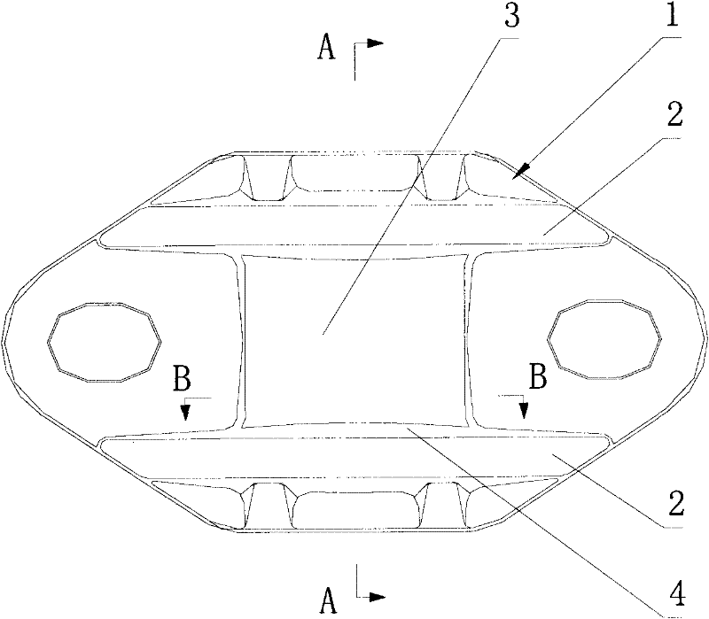
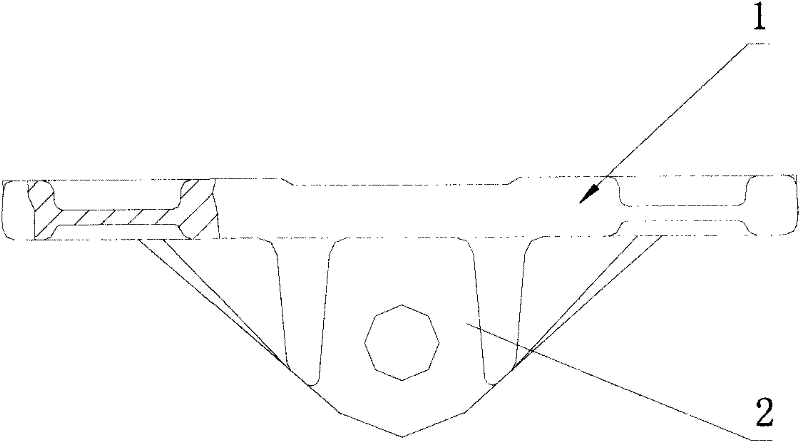
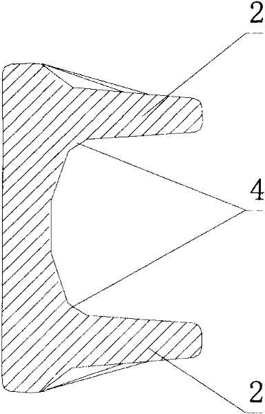
[0020] like Figure 5 As shown, a lower arm base of a route catenary support seat, the lower arm base is an integrated die forging as a whole. The die forging is obtained by deforming a blank using a die. During die forging, the pipe or bar is placed in the die forging cavity, and then radial pressure is continuously applied to achieve the deformation of the metal. The method of pressure die forging can be used, that is, the forging method of obtaining forgings by using dies to form blanks on die forging equipment (hammer die forging, crank press die forging, flat forging machine die forging or friction press die forging, etc.) , the integrated die forging can not only save metal and realize precision forging, but also requires equipment with simple structure, low cost and convenient maintenance.

[0021] like Figure 1 to Figure ...


PUM


Abstract

The invention discloses a lower cantilever base for a support seat of a railway line contact network. The whole lower cantilever base is an integrated die forging. On a base body, a boss is arranged between two installation plates; the surface of the boss is an indent and arc curved surface; the axis line of the indent and arc curved surface is parallel to the installation plates; and a circular arc transmission mode is adopted by the connection part of the boss and the installation plates. The lower cantilever base is manufactured in a die forging mode, so that the mechanical properties such as intensity, rigidity and the like of the lower cantilever base are greatly improved; when the curved surface with radian of R45 to 80 mm and the circular arc with radian of R5 to 15 mm are stressed, the force can be quickly transferred to the base body, the crack is prevented from generating on the curved surface under the condition that the shaking is enhanced, the service life of the lower cantilever base is prolonged and the replacement and maintenance cost is reduced; simultaneously, the implementation of the die forging mode is facilitated and the forging cost is reduced; and the lower cantilever base has a reasonable structure, and high intensity, and meets the requirements of the safety travelling of rapid trains which have a speed per hour of 250 to 350h / km or have a higher speed; and the travelling safety coefficient of the rapid trains is high.

Description

technical field [0001] The invention relates to an accessory part of a catenary support seat of a railway line, in particular to a lower arm base of the support seat of a catenary line of a railway line. Background technique [0002] The lower arm base of the catenary support seat of the railway line, as an important part of the catenary of the railway line, plays an important role in ensuring the safe running of the train. [0003] In the prior art, the base of the lower wrist arm of the catenary support base of the railway line is a casting formed by a casting process, and the base body is provided with two parallel mounting plates for mounting the rotating flat ears. It is a plane, and the transition between the plane and the mounting plate is through an arc surface with a radian R of 2mm. With the increase of railway speed, the train speed has reached 250~350h / km now, and it may reach higher in the future, so the frequency of catenary oscillations on railway lines will ...

Claims


Application Information

Patent Timeline
Patent Type & Authority Applications(China)
IPC IPC(8): B60M1/20
Inventor 顾良
Owner CHONGQING ZHONGCHENG PRECISION DIE FORGING
Why Eureka
Try Eureka