Pre-synchronization unit for transmission

A technology of pre-synchronization unit and transmission, applied in the direction of clutches, mechanical drive clutches, mechanical equipment, etc., can solve the problems of expensive and expensive manufacturing technology, and achieve the effects of durable mechanical resistance, high mechanical resistance, and low cost

Active Publication Date: 2016-03-02
HOERBIGER ANTRIEBSTECHN HLDG
View PDF8 Cites 0 Cited by
  • Summary
  • Abstract
  • Description
  • Claims
  • Application Information

AI Technical Summary

Problems solved by technology

The production of the conical synchronizing rings of the prior art is complex in terms of production technology and is therefore expensive

Method used


Image

  • Pre-synchronization unit for transmission
  • Pre-synchronization unit for transmission
  • Pre-synchronization unit for transmission

Examples


Embodiment Construction

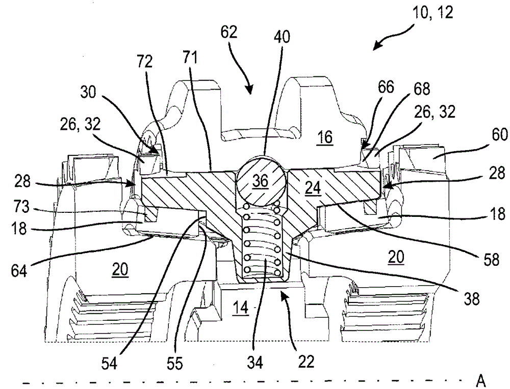
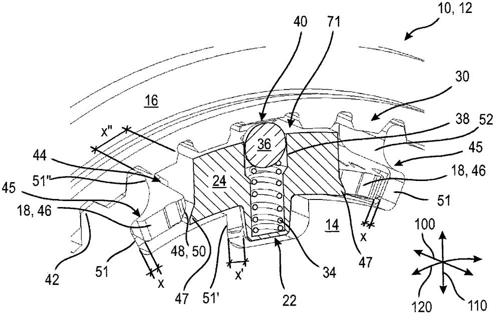
[0037] figure 1 and 2 A longitudinal or cross-sectional detail of the inertial synchronizing assembly 10 through the transmission 12 is shown. Here, the inertial synchronizing assembly 10 comprises: an annular synchronizing body 14 , which is mounted in a rotationally fixed manner on a shaft (not shown) of the transmission 12 ; a shifting sleeve 16 , which Arranged in a rotationally fixed manner relative to the synchronizing body 14 , but axially displaceable; a synchronizing ring 18 for coupling the synchronizing body 14 to a gear wheel of the transmission 12 via a frictional connection; and a presynchronization unit 22 which acts A synchronizer ring 18 is acted axially on the selector sleeve 16 and during an axial displacement of the selector sleeve 16 . here, in figure 1 The gears themselves are not shown, but only the clutch body 20 , which is connected to said gears in a rotationally fixed manner, and which has shift teeth 60 and friction surfaces 64 .

[0038] exist ...


PUM


Abstract

The invention relates to a presynchronization unit (22) of a transmission (12) having a stop block (24) which is accommodated in a mounted position around the drive axis in the presynchronization unit (22) (A) In the groove (44) of the rotating synchronous body (14), and adjacent to the gear shift sleeve (16) of the transmission (12) that is connected to the synchronous body (14) in a rotationally fixed manner, wherein the stopper (24) has a stop tooth (26), which allows or prevents the axial movement of the shift sleeve (16) relative to the stop block (24), and wherein the stop block (24) is Formed sheet metal part with stamped ratchet teeth (32). In this case, the radially outer surface (70) of the stop (24) can in particular be offset radially, so that said outer surface (70) is in the axially central region (71) more than in the area of ​​the ratchet teeth (32). It extends radially wider in the region (72).

Description

technical field [0001] The invention relates to a presynchronization unit of a transmission and an inertial synchronization assembly with such a presynchronization unit. Background technique [0002] In the prior art, for example, from the textbook "Fachkunde Kraftfahrzeugtechnik" ("Automotive Technology Expertise") (Europa-Lehrmittel Publishing House, 26th Edition, 1999, page 396 onwards), a transmission with an inertial synchronization device is known, In particular transmissions such as the Borg-Warner system. In conventional synchronizing devices of the inertial type, a synchronizing ring is always provided with locking teeth, wherein the locking teeth prevent a shifting connection to the synchronizing body in a rotationally fixed manner until the rotational speeds between the synchronizing body and the gear are synchronized. Axial movement of the clutch over the shift teeth of the gear. The rotationally fixed coupling of the synchronizing body to the gearwheel via the...

Claims


Application Information

Patent Timeline
Patent Type & Authority Patents(China)
IPC IPC(8): F16D23/06
CPCF16D23/06F16D2023/0618
Inventor 埃罗尔·勒代茨基乔治·鲁普雷希特于尔根·宾德托马斯·施内尔泽
Owner HOERBIGER ANTRIEBSTECHN HLDG
Why Eureka
Try Eureka