
Display device based on micro-electromechanical system (MEMS) light valve and forming method thereof

A display device and light valve technology, applied in optics, optical components, static indicators, etc., can solve the problems of complex process and high manufacturing cost of the display device, and achieve the effects of reducing manufacturing cost, simple structure, and simplifying the manufacturing process

Active Publication Date: 2011-11-09
XIAN YISHEN OPTOELECTRONICS TECH CO LTD
View PDF4 Cites 5 Cited by
  • Summary
  • Abstract
  • Description
  • Claims
  • Application Information

AI Technical Summary

Problems solved by technology

[0006] Provide a display device based on a MEMS light valve and its forming method, and solve the problems of complex process and high manufacturing cost of the existing TFT-MEMS light valve display device

Method used


Image

  • Display device based on micro-electromechanical system (MEMS) light valve and forming method thereof
  • Display device based on micro-electromechanical system (MEMS) light valve and forming method thereof
  • Display device based on micro-electromechanical system (MEMS) light valve and forming method thereof

Examples


Embodiment Construction

[0060] In order to make the above objects, features and advantages of the present invention more comprehensible, specific implementations of the present invention will be described in detail below in conjunction with the accompanying drawings.

[0061] A display device according to a specific embodiment of the present invention will be described in detail below in conjunction with specific embodiments.

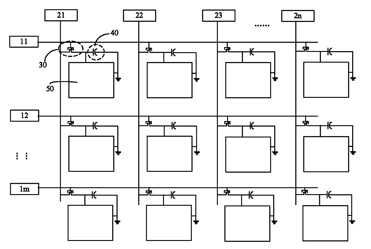
[0062] figure 1 It is a schematic diagram of the circuit structure of a display device based on a MEMS light valve. Such as figure 1 As shown, the display device in this embodiment includes: a substrate, a plurality of scanning lines 11, 12, ..., 1m located on the substrate, and a plurality of data lines 21, 22, ... . . . 2n, multiple MEMS switches 30 , capacitors 40 and MEMS light valves 50 located on the substrate; multiple scanning lines are parallel to each other, multiple data lines are parallel to each other, and the data lines and the scanning lines are perpendicular ...


PUM


Abstract

The invention provides a display device based on a micro-electromechanical system (MEMS) light valve. The display device comprises a substrate, and an MEMS switch and the MEMS light valve which are arranged on the surface of the substrate, wherein the MEMS switch comprises a first electrode, a third electrode, and a second electrode which is arranged relative to the first electrode and the third electrode; the second electrode is provided with a contact protrusion relative to the third electrode; and when a potential difference exists between the first electrode and the second electrode, the second electrode approaches the third electrode under the action of an electrostatic force, so that the contact protrusion contacts the third electrode so as to control the MEMS light valve through the MEMS switch. The invention also provides a forming method for the display device based on the MEMS light valve. In the display device, the MEMS switch replaces a thin-film transistor (TFT) switch tocontrol a display signal of the display device; and the MEMS switch is simple in structure, so that a manufacturing process of the display device is simplified and the manufacturing cost of the display device is reduced.

Description

technical field [0001] The invention relates to the field of semiconductor manufacturing, in particular to a display device based on a MEMS light valve and a forming method thereof. Background technique [0002] Liquid crystal flat panel display, especially TFT-LCD, is a display device that catches up with and surpasses CRT in terms of comprehensive performance such as brightness, contrast, power consumption, life, volume and weight. It has excellent performance, good mass production characteristics, and automatic High degree, low cost of raw materials, broad development space, may be the mainstream product of the next generation of displays. [0003] The liquid crystal display device mainly includes: a substrate, in which a backlight source is provided; pixel electrodes are located on the substrate, and a TFT (thin film transistor switch) array is also provided on the substrate, and the TFT (thin film transistor switch) array is used to communicate with the pixel The elect...

Claims


Application Information

Patent Timeline
IPC IPC(8): G02B26/02G09G3/34
Inventor 毛剑宏唐德明
Owner XIAN YISHEN OPTOELECTRONICS TECH CO LTD
Features
  • Generate Ideas
  • Intellectual Property
  • Life Sciences
  • Materials
  • Tech Scout
  • Unparalleled Data Quality
  • Higher Quality Content
  • 60% Fewer Hallucinations
Learn More