Protection element

A technology for protecting components and protecting objects, which is applied to electrical components, contacts, electrical switches, etc., can solve the problems of high manufacturing costs, difficulty in melting the fusible conductor 3, and prolonged time, so as to achieve low environmental burden and prevent active The effect of unevenness and size reduction

Active Publication Date: 2011-11-09
DEXERIALS CORP
View PDF4 Cites 10 Cited by
  • Summary
  • Abstract
  • Description
  • Claims
  • Application Information

AI Technical Summary

Problems solved by technology

At this time, the molten metal of the soluble conductor 3 tends to flow into other parts that can hold the flux 9, and the soluble conductor 3 is difficult to melt in the part where the flux 9 is insufficient, so that it is completely fused. The problem that the time required until now will be extended
[0011] Furthermore, as in the invention disclosed in Patent Document 1, when two or more low-melting-point metal bodies or a low-melting-point metal body with slits are formed, the above-mentioned halogen-free flux etc. The problem caused by the low activity flux, and further, the formation of slits, etc., requires a special mold in the manufacture of the protective element, making the manufacturing cost higher

Method used


Image

  • Protection element
  • Protection element
  • Protection element

Examples


Embodiment Construction

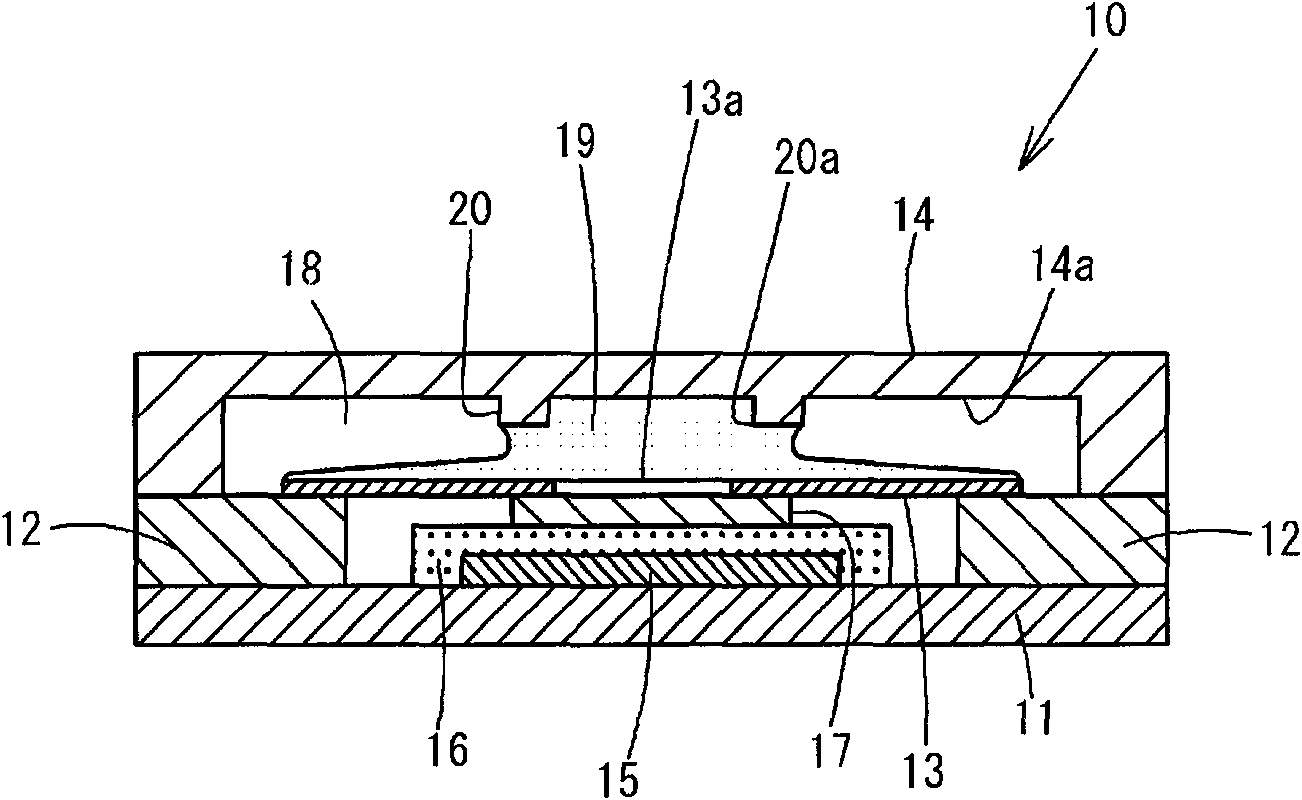
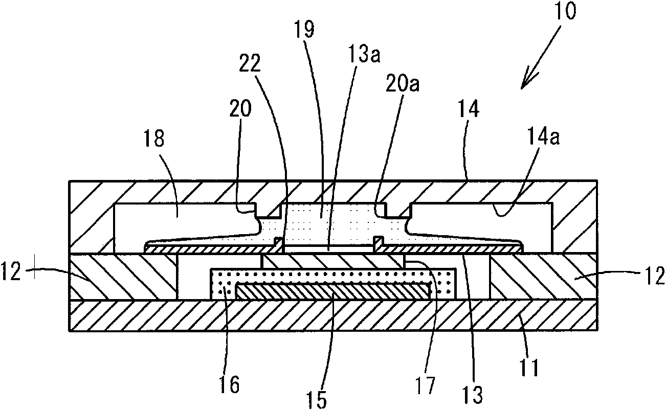
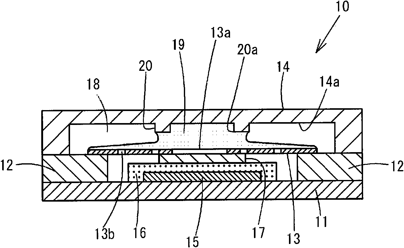
[0048] Hereinafter, for the first embodiment of the protection element of the present invention, according to Figure 1 to Figure 5 Be explained. The protective element 10 of this embodiment has a pair of electrodes 12 formed on both ends of the upper surface of an insulating base substrate 11 , and another pair of electrodes 21 is also provided on opposing edges perpendicular to the pair of electrodes 12 . Between the electrodes 21, a heating element 15 made of a resistor is connected. A conductive layer 17 connected to one of the electrodes 21 is laminated on the heating element 15 via the insulating layer 16 . On the conductor layer 17, the central part of the fusible conductor 13 of the fuse made of low-melting-point metal connected to the pair of electrodes 12 is connected. Furthermore, an insulating cover 14 made of an insulator is provided on the base substrate 11 so as to face the soluble conductor 13 .

[0049] As the material of the base substrate 11 , any material ...


PUM


Abstract

Provided is a protection element wherein a flux on a soluble conductor can be stably held at a predetermined position and the soluble conductor can speedily and accurately fuse when abnormality occurs. The protection element has: a soluble conductor (13), which is arranged on an insulating base substrate (11), is connected to the power supply line of an apparatus to be protected and fuses with a predetermined abnormal power; a flux (19) applied on the surface of the soluble conductor (13); and an insulating cover (14) which covers the soluble conductor (13) and is attached to the base substrate (11). The protection element is provided with a protruding strip section (20), which is formed on the inner surface of the insulating cover (14) by facing the soluble conductor (13) and has a step section (20a) which is in contact with the flux (19) and holds the flux (19) at the predetermined position. The soluble conductor (13) is provided with a hole section (13a) which holds the flux (19) therein.

Description

technical field [0001] The present invention relates to a protection element that cuts off the current by melting a fusible conductor due to the heat when excessive current or voltage is applied to electronic equipment or the like. Background technique [0002] Conventionally, as protection elements mounted on secondary battery devices and the like, not only protection elements having an overcurrent prevention function but also protection modules having an overvoltage prevention function have been used. This protection element is composed of the following form. A heating element and a fusible conductor composed of a low-melting-point metal body are laminated on the substrate, and the fusible conductor is fused by an overcurrent, and at the same time, it can also protect against the overvoltage when an overvoltage is generated. The heating element inside the protection element is energized so that the fusible conductor is fused by the heat of the heating element. The melting...

Claims


Application Information

Patent Timeline
Patent Type & Authority Applications(China)
IPC IPC(8): H01H37/76
CPCH01H2037/768H01H37/761H01H1/5805H01H37/76Y10T29/49107
Inventor 木村裕二浅田隆广铃木和明
Owner DEXERIALS CORP
Why Eureka
Try Eureka