Energy-saving travelling type hydraulic transport machine

A kind of moving machinery and walking technology, which is applied in the field of energy-saving walking hydraulic handling machinery, which can solve the problems of limited potential energy recovery, short landing process time, inability to adapt to changes in potential energy, etc.

Inactive Publication Date: 2011-11-16
JINAN JENHANG ENERGY SAVING TECH
View PDF9 Cites 41 Cited by
  • Summary
  • Abstract
  • Description
  • Claims
  • Application Information

AI Technical Summary

Problems solved by technology

Some recent information and reports also reflect this trend, such as the patent application No. 200810143874.7 entitled "A Method and Device for Recovery of Potential Energy of Hydraulic Excavator Arm", etc. The common point of these technical solutions is to convert the potential energy of heavy objects During the lowering process, the electrical energy is converted into electrical energy by the generator and stored in the battery or super capacitor. Their problems are: the time of the lowering process is very short, the ordinary battery has no time to charge, and the recovered potential energy is limited; while the super capacitor and large-capacity lithium battery There are many bottlenecks in terms of economy, technology and lifespan, and there is still a long way to go before widespread practical application
The patent application number is 200710120715.0, which is called power generation state energy reuse electrohydraulic energy-saving beam pumping unit, which directly stores a small part of the potential energy when the motor is in power generation mode during the descending process of the "donkey head" through the descending oil cylinder. In the hydraulic accumulator, it is directly put into the oil cylinder to assist when lifting. It is only suitable for machines with basically constant potential energy, and cannot adapt to ordinary hydraulic handling machines with variable potential energy.

Method used


Image

  • Energy-saving travelling type hydraulic transport machine
  • Energy-saving travelling type hydraulic transport machine
  • Energy-saving travelling type hydraulic transport machine

Examples


Embodiment approach

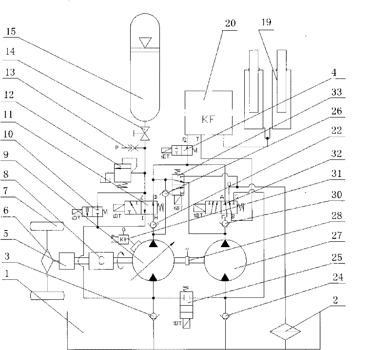
[0043] Now in conjunction with the accompanying drawings to illustrate the specific implementation of the present invention, the combined system of the variable pump and the quantitative motor is shown in figure 1, is a better adaptive solution, which can automatically adapt to potential energy recovery under different working conditions. When the driver uses power machinery (diesel engine or electric motor) 8 to drive the variable oil pump 9 to drive the lifting cylinder 19 to lift heavy objects, if the driver controls the machine Carry out the lowering operation, in the process of lowering the heavy object, the oil in the lower chamber (rodless chamber) of the lifting cylinder 19 is pressed to the unblocked (flow resistance adjusted to the minimum) return of the control valve group 20 by the gravity of the heavy object. Oil channel T, at the same time, 1DT and 5DT are energized, the reversing valves 11 and 32 are reversing, and the pressured return oil passes through the B po...


PUM


Abstract

The invention relates to an energy-saving travelling type hydraulic transport machine. According to the invention, an added hydraulic element and an original hydraulic system of the transport machine are used for partially converting potential energy before dropping down a heavy object and kinetic energy before braking a vehicle to pressure energy of fluid and storing the pressure energy in a hydraulic energy accumulator during the frequent lifting, dropping-down, braking and starting processes of the travelling type hydraulic transport machine, and the stored pressure energy is used for lift the heavy object and start the vehicle next time, so that the mechanical energy (the potential energy and the kinetic energy) obtained by power consumption can be regenerated partially, thereby reducing load and power of a power machine for driving an oil pump and starting the vehicle; since the potential energy of the heavy object and the kinetic energy of the vehicle, which are obtained by power consumption, can be partially regenerated during the process of re-lifting the heavy object and re-starting the vehicle, high recovery and regeneration efficiency can be achieved and the effects of energy saving and emission reducing are very remarkable. The energy-saving travelling type hydraulic transport machine is simple and easy to operate and has the advantages of low investment and long service life. The energy-saving travelling type hydraulic transport machine can be configured during new construction or added during transformation of the old machine.

Description

Technical field: [0001] The energy-saving walking hydraulic handling machine of the present invention uses the added hydraulic components and the original hydraulic system of the handling machine to move the heavy objects during the process of frequent lifting, lowering, braking and starting of the walking hydraulic handling machine. The potential energy before lowering and the kinetic energy of the vehicle before braking are partially converted into the pressure energy of the fluid and stored in the hydraulic accumulator, and used for lifting heavy objects and starting the vehicle next time, so that the mechanical energy obtained by consuming power (potential energy and kinetic energy) is partially regenerated. This energy-saving walking hydraulic handling machine includes the driving system and control system for lifting and walking, and some hydraulic components are added to the original hydraulic system to form a new hydraulic system. It is characterized in that it has at ...

Claims


Application Information

Patent Timeline
Patent Type & Authority Applications(China)
IPC IPC(8): B66F9/06B66F9/22F15B21/14
CPCF15B2211/20576E02F9/2296F15B1/024E02F9/2217F15B2211/20507F15B21/14B66F9/22F15B2211/20546E02F9/2292F15B2211/20569B60K6/12E02F9/2246Y02T10/62B66F9/06F15B11/00
Inventor 江绍成姚航白瑞海张桂珍
Owner JINAN JENHANG ENERGY SAVING TECH
Why Eureka
Try Eureka