Winding device and method of spiral wires for traveling wave tubes and winding method

A helix and winding technology, applied in the field of microwave vacuum devices, can solve the problems of difficulty in guaranteeing the inner and outer diameter and pitch accuracy of the helix, affecting the production efficiency and working performance of the traveling wave tube, and poor winding performance, etc. Pitch accuracy, ensure production efficiency and work performance, and ensure the effect of inner and outer diameter accuracy

Active Publication Date: 2011-11-16
HUADONG PHOTOELECTRIC TECHN INST OF ANHUI PROVINCE
View PDF1 Cites 11 Cited by
  • Summary
  • Abstract
  • Description
  • Claims
  • Application Information

AI Technical Summary

Problems solved by technology

The metal wire material for winding the helix is ​​generally refractory metal molybdenum, tungsten, etc., and its winding performance is poor. The current winding method is difficult to guarantee the inner and outer diameters and pitch accuracy requirements of the helix, which in turn affects the traveling wave tube. Productivity and work performance

Method used


Image

  • Winding device and method of spiral wires for traveling wave tubes and winding method
  • Winding device and method of spiral wires for traveling wave tubes and winding method
  • Winding device and method of spiral wires for traveling wave tubes and winding method

Examples


Embodiment Construction

[0029] The specific implementation manner of the present invention will be described in further detail below by describing the best embodiment with reference to the accompanying drawings.

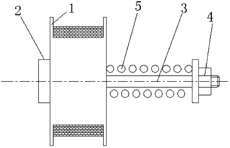
[0030] The winding device for the helical wire for traveling wave tubes includes a lathe, on the tool rest of the lathe, a mounting jig for installing the entire strip is connected, on the jig of the lathe, a core rod is installed, on the mounting jig and the A tensioning fixture is provided between the core rods, and one end of the whole strip drawn out bypasses the tensioning clamps to reach the position of the core rods and is fixed on the core rods.

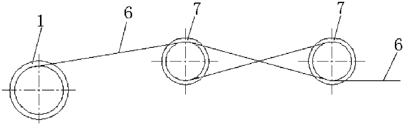
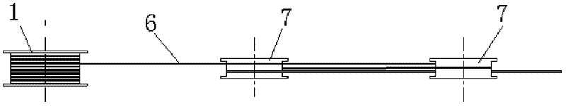
[0031] Figure 1 to Figure 4 It is a structural schematic diagram of the installation jig, tensioning jig and core rod in the winding device of the helical wire for traveling wave tubes.

[0032] Such as figure 1 As shown, the installation fixture includes a bracket 2 and a bracket shaft 3, one end of the bracket shaft 3 is connected to ...


PUM


Abstract

The invention discloses a winding device and method of spiral wires for traveling wave tubes. The winding device of the spiral wires for the traveling wave tubes comprises a lathe, wherein an installing fixture, which is used for installing a whole disc of belt material, is connected on a tool rest of the lathe; a core bar is arranged on the fixture of the lathe; a tensioning fixture is arranged between the installing fixture and the core bar; and one end drawn out from the whole disc of belt material bypasses the tensioning fixture to reach the position of the core rod and is fixed on the core rod. The winding method of the spiral wires for the traveling wave tubes comprises the following steps of: with the winding device of the spiral wires for the traveling wave tubes, enabling a certain tensile force to exist between one end drawn out from the belt material and the whole disc of belt material by the tensioning fixture; manually rotating the core rod to ensure that few loops of thebelt material are wound on the core rod; tensioning and straightening the tail end of the core rod by the fixture at the tail end of the lathe; starting the lathe, rotating the core rod rotates, enabling the installing fixture to move axially along the lathe, wounding the belt material on the core rod along with the rotation of the core rod; controlling the rotating speed of the core rod and themoving speed of the installing fixture, and ensuing the accuracy requirements on pitches of the spiral wires.

Description

technical field [0001] The invention relates to the field of microwave vacuum devices, in particular to a winding device and a winding method for a helical wire for a traveling wave tube. Background technique [0002] In the microwave field, the traveling wave tube is the best device that combines bandwidth and gain. Among them, the helical traveling wave tube is the most widely used, and its high-frequency circuit is generally a helical metal wire or metal strip, which consists of three or More dielectric rods are clamped and secured within the metal tubular casing. The basic role of the helical wire is to provide a high-frequency electromagnetic wave with an axial propagation speed close to the electron motion speed and a sufficiently strong axial electric field, so that the electromagnetic wave interacts with the electron beam to amplify the signal. The helical wire is usually called a helix, which is the carrier of high-frequency energy and electron beam energy exchange...

Claims


Application Information

Patent Timeline
Patent Type & Authority Applications(China)
IPC IPC(8): H01J9/00
Inventor 吴华夏贺兆昌张文丙朱刚周秋俊袁璟春董晨王瑞
Owner HUADONG PHOTOELECTRIC TECHN INST OF ANHUI PROVINCE
Why Eureka
Try Eureka