Electrodeless illuminating lamp
A technology for lighting lamps and light-emitting tubes, which is applied in the field of lighting lamps, can solve the problems that the heat of lamps cannot be dissipated well, there is no cooling and cooling device, and the service life is affected, and the effects of simple structure, prolonged service life and high light efficiency are achieved.
- Summary
- Abstract
- Description
- Claims
- Application Information
AI Technical Summary
Problems solved by technology
Method used
Image
Examples
Embodiment 1
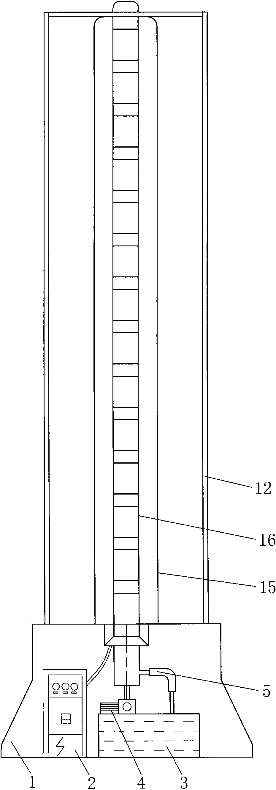
[0017] Embodiment 1: as figure 1 As shown, the present invention includes a base 1 with a built-in electric control cabinet 2 and a cooling system, a bracket 12, a luminous tube 15 and a coupler 16, the bracket 12 is placed on the base 1, and the luminous tube 15 is installed on the base 1 in the bracket 12. And respectively connected with the electric control cabinet 2 and the cooling system, the coupler 16 is placed in the luminous tube 15, and the positive and negative poles of the coil 13 are respectively connected with the electric control cabinet 2.
[0018] Such as figure 2 As shown, the coupler 16 of the present invention includes an inner water pipe 11, an outer water pipe 18, a coil 13, multiple sets of magnets 8 and magnetic isolation sleeves 9, wherein the number of sets of magnets 8 is determined according to user needs, and four are selected in this example , the magnets 8 separated by magnetic isolation sleeves 9 are set on the outer water pipe 18, the coil 13...
Embodiment 2
[0022] Embodiment 2: The overall structure of this example is the same as that of Embodiment 1, but the difference is that there are 10 magnets 8 in the coupler 16 of this example, and the winding method of its coil 13 and the installation method of the magnets 8 are the same as those of Embodiment 1, namely: The magnetic poles of the two adjacent magnets 8 are the same, and the winding methods of the coils 13 are opposite. Wherein the inner water pipe 11, the outer water pipe 18 are connected to the cooling system as follows: the water nozzle 14 of the outer water pipe 18 is connected to the water outlet of the water pump 4 through the water pipe, and the inner water pipe 11 is connected to the water tank 3, then the water circulation is: in the water tank 3 The water enters the outer water pipe 18 through the water pump 4, flows out to the water tank through the inner water pipe 11, and completes the water cooling cycle.
Embodiment 3
[0023] Embodiment 3: The overall structure of this example is the same as that of Embodiment 1, but the difference is that there are 14 magnets 8 in the coupler 16 of this example, and the winding method of its coil 13 and the installation method of the magnets 8 are the same as those of Embodiment 1, that is: The magnetic poles of the two adjacent magnets 8 are the same, and the winding methods of the coils 13 are opposite.
PUM
 Abstract
Description
Claims
Application Information
 - R&D
- Intellectual Property
- Life Sciences
- Materials
- Tech Scout
- Unparalleled Data Quality
- Higher Quality Content
- 60% Fewer Hallucinations
Browse by: Latest US Patents, China's latest patents, Technical Efficacy Thesaurus, Application Domain, Technology Topic, Popular Technical Reports.
© 2025 PatSnap. All rights reserved.Legal|Privacy policy|Modern Slavery Act Transparency Statement|Sitemap|About US| Contact US: help@patsnap.com


