
Supply apparatus and power supply method

A technology of power supply and power supply device, which is applied in the direction of high-efficiency power electronic conversion, output power conversion device, electrical components, etc. It can solve the problems of unreachable and large power consumption, and achieve low input current and fast start-up voltage establishment. Boot effect

Inactive Publication Date: 2011-11-16
LIEN CHANG ELECTRONICS ENTERPRISE
View PDF4 Cites 9 Cited by
  • Summary
  • Abstract
  • Description
  • Claims
  • Application Information

AI Technical Summary

Problems solved by technology

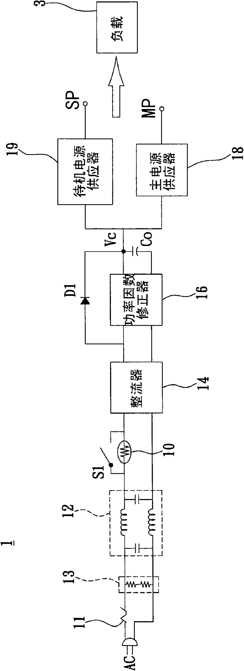
In the standby power supply mode, the bleeder resistor 13 and the filter 12 in the conventional power supply device 1 will generate a relatively large power consumption, especially the filter 12 including the inductance element and the capacitor element will generate a relatively large power consumption in the standby power supply mode. huge power consumption
Therefore, the standby power consumption of the traditional power supply device 1 is still unable to reach the current scheme adopted by the International Energy Agency (IEA) and promoted by various advanced countries and regions in the world to "reduce the standby power of a single electrical product to 0.1W".

Method used


Image

  • Supply apparatus and power supply method
  • Supply apparatus and power supply method
  • Supply apparatus and power supply method

Examples


Embodiment Construction

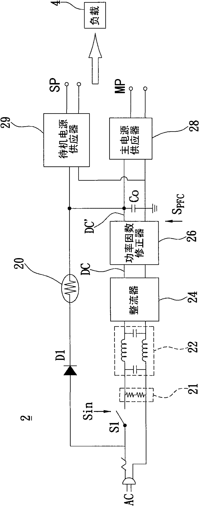
[0055] refer to figure 2 . figure 2 It is a schematic block diagram of a circuit of a power supply device according to an embodiment of the present invention. The power supply device 2 can be installed in an electrical product (not shown) to provide power for a load 4 in the electrical product. The electrical product can be a thin TV screen or other related displays, and the load 4 can be an LED lamp driving circuit.

[0056] Refer again figure 2 . When the plug of the electrical product is inserted into the socket, the alternating current AC with surge current will be fed into the power supply device 2 of this embodiment, and the power supply device 2 can effectively suppress the surge current to protect the back-end load 4, and , to provide a standby power supply SP for the load 4 to use during standby. In addition, the power supply device 2 is controlled by a switch control signal Sin and a power factor correction control signal S PFC , to provide a main power MP f...


PUM


Abstract

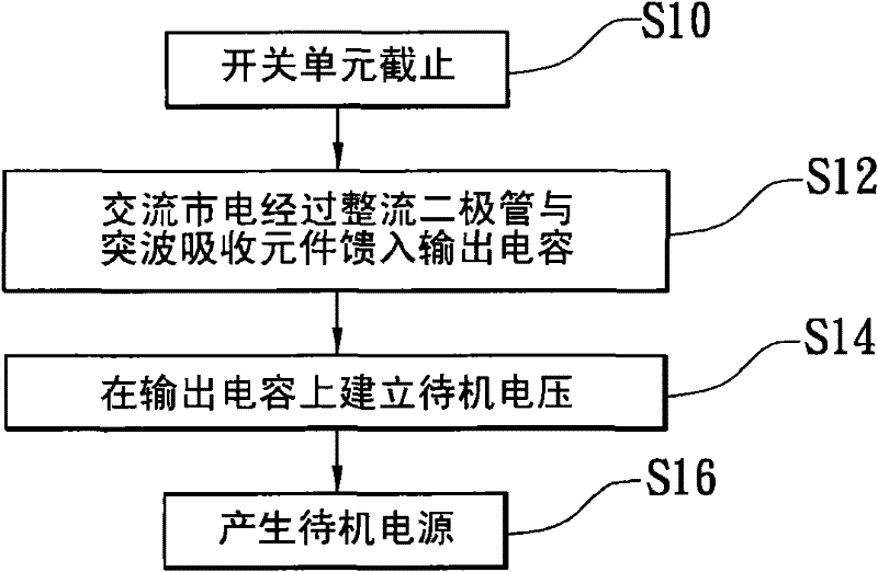
The invention discloses a supply apparatus and a power supply method. The supply apparatus comprises a switching unit, a bleeder resistor, a filter, a rectifier, a power factor corrector, an output capacitor, a rectifying diode, a surge absorber element, a main power supply unit and a standby power supply unit, wherein when the switching unit is switched off, AC (alternating current) mains electricity is used for charging the output capacitor by the rectifying diode and the surge absorber element so as to supply for the standby power supply unit and then the standby power supply unit generates a standby power supply; and when the switching unit is switched on, the AC mains electricity is used for charging the output capacitor by the switching unit, the bleeder resistor, the filter, the rectifier and the power factor corrector so as to supply for the main power supply unit and then the main power supply unit generates a main power supply. The supply apparatus can restrain surge currents effectively, reduce the standby power consumption and meet the energy-saving requirement.

Description

technical field [0001] The invention relates to a power supply device and a power supply method, in particular to a power supply device and a power supply method capable of saving electricity when an electrical product is in standby. Background technique [0002] Generally speaking, a power supply device and a load are usually installed in an electrical product, wherein the power supply device converts the AC mains power into the power required by the load. However, this kind of power supply device is quite fragile, and it is very easy to be affected by instantaneous high voltage surges on the power, which will generate a large current and cause damage to the back-end load. Aiming at this phenomenon, the current solution is to use a surge absorbing element and a fuse to suppress the instantaneous surge voltage. Please refer to figure 1 . figure 1 It is a schematic block diagram of a conventional power supply device. [0003] The conventional power supply device 1 can wor...

Claims


Application Information

Patent Timeline
IPC IPC(8): H02M7/04H02M1/12H02M1/42
CPCY02B70/126Y02B70/10
Inventor 陈振刚游志平
Owner LIEN CHANG ELECTRONICS ENTERPRISE
Learn More